System Description
The Ethylene Oxide (EO) chamber is used to treat product using EO. The chamber is controlled by a PLC.
The EO Control System is used to accept user input regarding various parameters that control product processing in the chamber, to log information related to user actions, to control the material handling system, and to control process. The AccuSOLO control system controls one EO chamber, see section Chambers and the required plant utilities, see section Plant Utilities.
Chambers
The AccuSOLO control system is designed to control one EO chamber. A chamber is a sealed vessel which processes product with Ethylene Oxide (EO) gas. An initial vacuum is relieved with EO and held for a defined exposure period. After exposure, successive vacuum cycles, each relieved with dry nitrogen, dilute the EO concentrations and remove residue due to exposure. Exhaust from the chamber vacuum system is taken to an EO pollution control system to comply with safety and environmental standards. The control system will process product in the chamber according to a user defined cycle.
Plant Utilities
Plant utilities consists of equipment which is required by the process but provided by the plant, such as Steam, Process Water, Chilled Water, Instrument Air, Nitrogen, Breathable Air, Scrubber and AC Power. No plant utilities are controlled by the AccuSOLO control system.
Minimum System Components
The EO Control System will consist of several hardware components working together to reliably fulfil the control system functional requirements. In order to support the EO Control System, the SCADA PC will meet the minimum requirements, defined in the table, below.
|
Item |
Hardware |
Software |
|---|---|---|
|
AccuSOLO Client PC |
8 GB RAM Intel i3 or better (10th generation or newer), OR Ryzen 3 or better (3rd generation or newer) Two 23” 1920x1080 monitors (1920x1200 recommended) 250 GB HDD |
Windows 10, 11; 64-bit |
|
Printer (optional) |
Office grade laser jet printer |
|
|
PLC |
Allen-Bradley CompactLogix 5370 1769-L36ERM (CompactLogix 5380 5069-L340ER recommended) PLC |
AccuSOLO Process Control |
|
Distributed Inputs and Outputs (if required) |
1719 series Remote I/O OR 1734 Point I/O |
None |
|
SQL Server |
16 GB RAM 4 cores 2.2 GHz min 150 GB HDD OS, 100 GB HDD DB Data, 100 GB HDD DB Log, 1 TB HDD Local Backup |
Windows Server 2016 or newer SQL Server 2014 or 2022 Standard Edition (5 CALs) |
|
Remote SQL Server Backup |
2 TB Remote DB Archive |
|
|
App Server |
12 GB RAM 4 cores 2.2 GHz min 200 GB HDD minimum RAID 1 min |
Windows Server 2016 or newer
|
System Architecture
The following system architecture is used by the system:
PC and Database
-
User Interface
-
Stores Process Data
Printer
-
Reports
PLC
-
Real time process control
-
Gathers status/information about the process using digital and analog inputs
-
Generates control signals to various actuators using digital and analog outputs
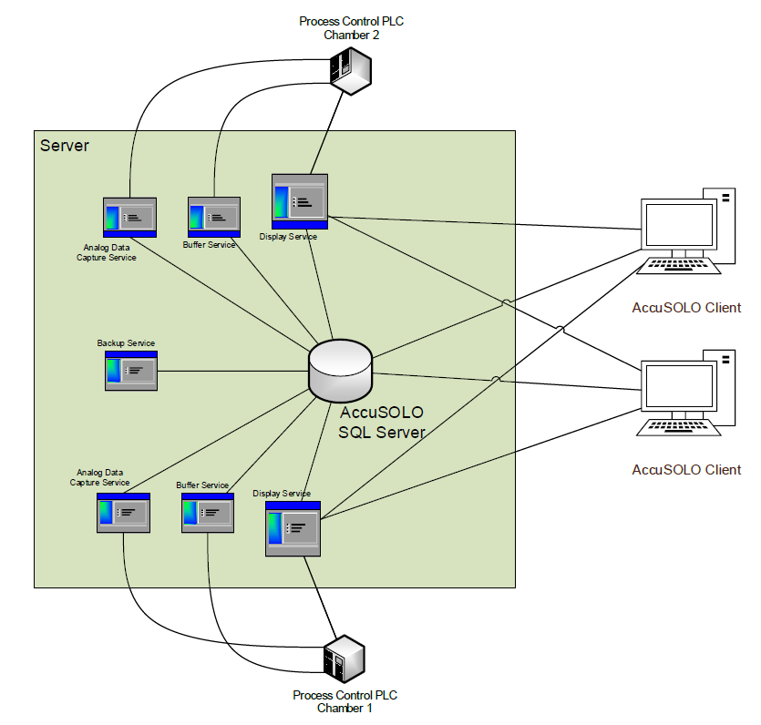
Typical Server Architecture
Server architecture for a site with two chambers is shown in System Description.
-
The database resides on a dedicated AccuSOLO SQL Server.
-
Two Client PCs are employed (one for each chamber, although each one can be configured to access both chambers).
-
Two PLCs are required, one for each chamber.
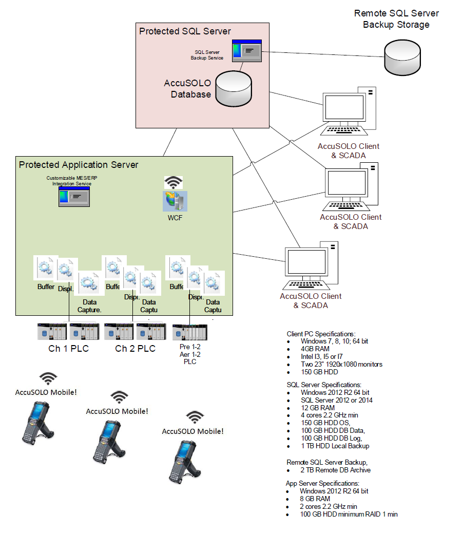
Server architecture for a site with two chambers, PCR/Aeration and separate SQL and App servers is shown in Figure 2 below:
-
The database resides on a dedicated AccuSOLO SQL Server.
-
SQL server backup service creates daily backups (for more information see section Full Backup)
-
-
AccuSOLO services run on a dedicated AccuSOLO App server.
-
Three PLCs are required, one for each chamber and one for PCR/Aeration.
The Client PCs, Process Control PLCs, and the database communicate with each other via services that run on the SQL Server:
-
Display Service – responsible for reading PLC inputs/outputs and displaying them graphically to the user on the Client PC
-
If there is a communication problem with the Display Service, the AccuSOLO Client Application will display a Communication Failed error on the screen and a “Server – PLC Communication timeout” Alarm 112 will be raised.

-
-
Buffer Service – responsible for copying PLC buffer records to the database. It is also used to restore a chamber state to the PLC in the disaster recovery procedure.
-
The PLC accumulates all events and run records in its own memory.
-
The PLC memory buffer is uploaded to the database via the Buffer Service.
-
Records are time stamped in real-time and no data is lost in case the database server, or the network, that facilitates data transport between the PLC and the server fails.
-
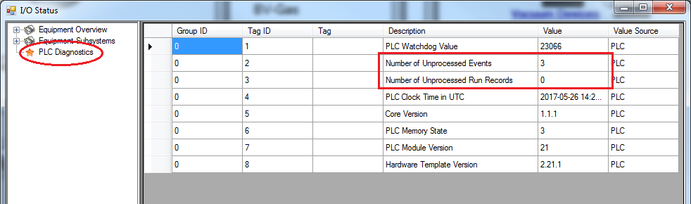
The buffer service is programmed to handle various network/server failures and is expected to recover automatically under a number of known conditions. However, should an unhandled failure of the Buffer Service occur, or if the network system prevents the Buffer Service from accessing the PLC or SQL Server, the AccuSOLO Client Application will display an error:

This error will be displayed if either of the following occurs:
-
Number of unprocessed events in the PLC has stagnated or increased over the span of 2.5 minutes.
-
Number of unprocessed records in the PLC is greater than 500.
-
-
Other symptoms that can be observed during a Buffer Service failure are as follows:
-
Physical alarm beacon turns on but no new alarms are shown on the display.
-
New events that should be showing on the Current/Historical Events are not appearing.
-
Previewed Run Records of runs in progress do not show all completed cycle steps.
-
A number greater than 0 of unprocessed events/run records is displayed on the PLC Diagnostics node of the I/O Status display:
-
-
The PLC memory buffer will eventually run out of its capacity to store data. This is dependant on the programmed frequency of run records and the number of events occurring in the system:
-
The conservative estimate is approximately 8 hours’ worth of run record and event data.
-
Once the PLC buffer fills up with 50 unprocessed events or run records, the alarm beacon will turn on.
-
Once the PLC buffer is 95% full, the chamber will be placed on a Maintained Hold and cannot be resumed until the buffer becomes freed up.
-
-
Once the Buffer Service recovers, it will attempt to catch up and restore any unprocessed events.
-
It the very unlikely scenario that the buffer service cannot recover automatically and needs manual restarting, you will need to contact your IT department. Konnexis assistance may be required.
-
-
Analog Data Capture Service – responsible for capturing sensor data from the PLC and making it available on the AccuSOLO charts. See section Charts for more information on charts.
-
Backup Service (DB Agent) – responsible for making database backups. See section Backup of the Database Log for more information.
User Interface Overview
When the AccuSOLO application launches, the following screen typically appears.
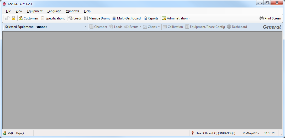
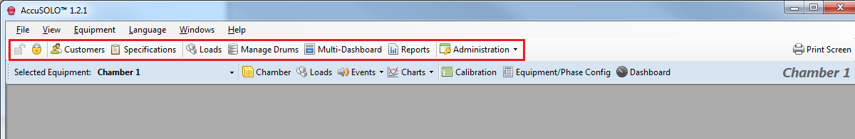
The top-most toolbar with icons, System Description is used to display screens with general site functions that are not specific to any equipment/chamber. This includes login/logout buttons, customer management, specifications, loads, drum management, multi-dashboard, reports, and administration (system and database configuration, user/group management, and primary standard management used in calibrations).
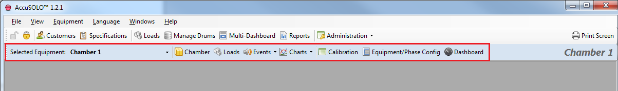
The equipment-based toolbar, System Description is used to display screens with functions that are specific to the selected equipment. This includes the Chamber P&ID screen (if available), loads (transfer or remove loads from the equipment), events (current and historical), charts, calibration, equipment/phase parameter configuration, and the dashboard.
License Management
If your AccuSOLO application is not licensed, the license activation pop-up will be presented:
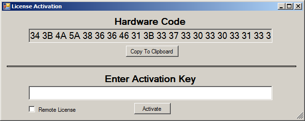
Select the entire Hardware Code and send it to KONNEXIS in order to obtain your activation key (you can use the “Copy to Clipboard” button to copy the entire hardware code and then paste it into an e-mail to be sent to KONNEXIS). Once KONNEXIS provides your activation key, enter it into the field and click the Activate button. Select the “Remote License” flag if you would like to run the client application in Remote mode, see Remote Mode. If the key is accepted, the application will obtain the appropriate licenses. The Remote flag can be toggled at any time from the “License Activations” pop-up, provided that the user has the administrator role.
The license management window will list which site, client, and equipment licenses are activated. It can be accessed via the Administration drop-down menu:
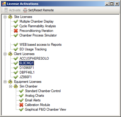
This pop-up also allows you to toggle the “Remote” flag for any of the client licenses see Remote Mode.
Remote Mode
The Remote flag allows for remote clients to connect to the system without the danger of impacting process directly. Setting the Remote flag will disable chamber control by not allowing the application to send any SCADA commands to the PLC (e.g. changing chamber mode, manually controlling valves, etc. will NOT be allowed). The “remote” client will still be able to perform all equipment monitoring, administration, and process set-up functions.