Chamber Configuration (Equipment/Phase Config)
Chamber Configuration Parameters
The chamber configuration parameters allow users with appropriate privilege level to configure specific parameters related to each chamber as described in the subsections below.
Note: Your site must have the appropriate I/O configuration in order to support certain parameters listed in this section. Please refer to your site’s Chamber System Functional Specification document to see a list of supported phases and associated I/O points.
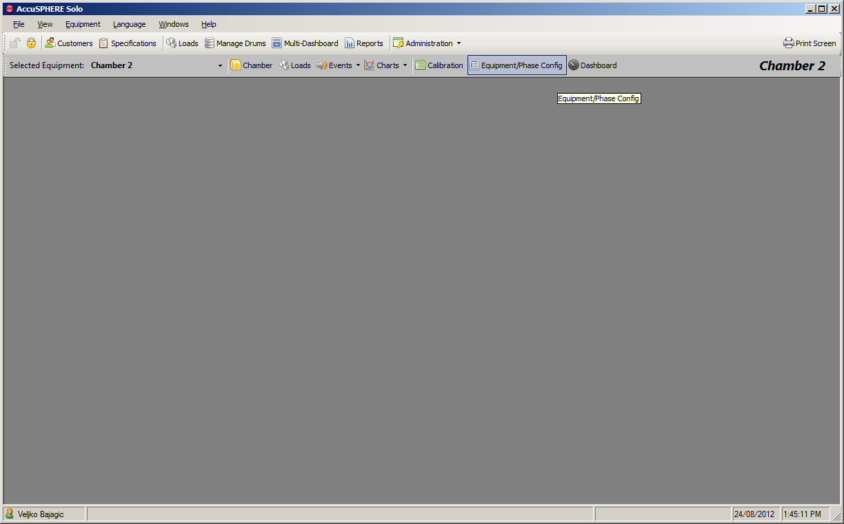
To access the Equipment/Phase Configuration form, select the desired equipment from the drop-down menu and then click “Equipment/Phase Config”:
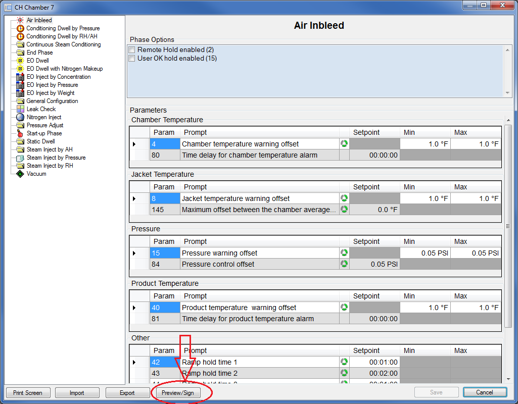
The Equipment Phase Parameters configuration form will be presented. The parameters flagged with the  icon can be modified during runtime:
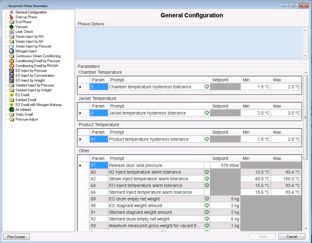
Make a change to any of the parameters and click Save.
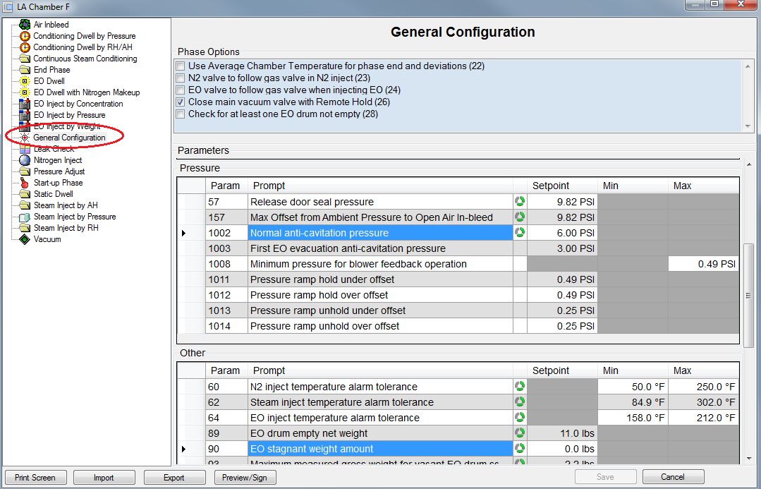
Miscellaneous General Configuration Parameters
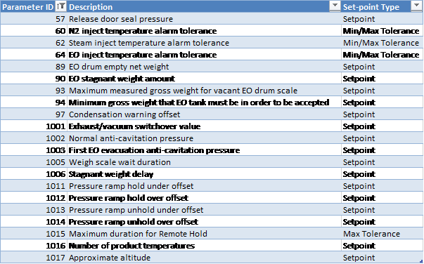
The following are some of the parameters that are available when the “General Configuration” node is selected:
-
Release door seal pressure [Parameter 57]: when chamber enters the End Phase:
-
the air in-bleed will allow the pressure to rise back up to this set-point; note that this is also the minimum pressure needed to open the door. See section Process for more information.
-
-
N2 inject temperature alarm tolerance [Parameter 60]: alarm conditions to ensure that the nitrogen temperature is within an acceptable range.
-
Steam inject temperature alarm tolerance [Parameter 62]: alarm conditions to ensure that the steam temperature is within an acceptable range.
-
EO inject temperature alarm tolerance [Parameter 64]: alarm conditions to ensure that the EO temperature is within an acceptable range.
-
The system will not allow inject to proceed if the temperature is not within this range.
-
-
EO drum empty net weight [Parameter 89]: indicates the amount above the tare weight of the EO drum at which the system will consider the drum to be empty and raise the empty drum alarm 92.
-
EO phases are not allowed to proceed if the empty drum alarm is active
-
Alarm 92 is only raised during an EO phase (EO Inject or EO Dwell) or at end-of-phase if the next phase is an EO phase (start-phase interlock)
-
-
EO stagnant weight amount [Parameter 90] and Stagnant Weight Delay [Parameter 1006]: indicates the amount by which the EO drum weight must change in a certain amount of time in order to not be considered stagnant.
-
If the cycle is in an EO Inject phase (via Pressure, Concentration or Weight) and EO valve(s) are commanded open, dependent on Inject Template configuration and the EO drum weight does not change by more than the amount in Parameter 90 for longer than the “stagnant weight delay” Parameter 1006 value, the system will raise the stagnant weight alarm
-
Stagnant Weight Delay [Parameter 1006] timer will be reset each time any of the EO valves close or when EO Stagnant Weight amount [Parameter 90] is reached.
-
The stagnant weight alarm is configured to place the chamber on Hold by default.
-
-
Parameters used for EO Drum Changes (see section Drum Change Sequence for more information):
-
“Maximum measured gross weight for vacant EO drum scale” [Parameter 93] is used to determine if a drum has been removed from the weigh scale:
-
When operator initiates the Remove Drum command during a drum change, the system will wait for the gross weight to fall below this value before considering the scale to be vacant (i.e. no drum is on the scale).
-
-
“Minimum gross weight that EO tank must be in order to be accepted” [Parameter 94] is used to determine if a new drum has been placed on the scale:
-
After a drum removal command is issued, the system will wait for the gross weight to be at least this amount before it allows the operator to assign a new drum ID to the scale.
-
-
-
Condensation warning offset [Parameter 97]: when the jacket temperature is lower than the chamber temperature by this amount, an alarm will be raised.
-
Exhaust/vacuum switchover offset [Parameter 1001]: if the chamber pressure is greater than the ambient pressure plus this offset amount, and if no EO has been admitted to the chamber, the system will use the vacuum exhaust valve (if installed) during the Vacuum phase
-
The system will switch back to using the vacuum subsystem when the chamber pressure drops below the ambient pressure plus this offset value, to continue the Vacuum phase.
-
This functionality is disabled if this parameter is not configured or set to zero (0)
-
-
Normal anti-cavitation pressure [Parameter 1002]: if the anti-cavitation valve is installed, it will close when the vacuum valve opens as long as the chamber pressure is above the value configured in this parameter.
-
When chamber pressure is below the “normal anti-cavitation pressure” the anti-cavitation valve will stay open regardless of the state of the vacuum valve.
-
-
First EO evacuation anti-cavitation pressure [Parameter 1003]: if the anti-cavitation valve is installed and the chamber is executing the first Vacuum phase after EO Inject/Dwell, it will close the anti-cavitation valve when the vacuum valve opens as long as the chamber pressure is above the value in this parameter.
-
When chamber pressure is below the “first EO evacuation anti-cavitation pressure”, the anti-cavitation valve will stay open regardless of the state of the vacuum valve.
-
-
Weigh scale wait duration [Parameter 1005]: after all EO subsystem valves have closed (e.g. at the end of EO Inject/Dwell phase or due to Hold/Stop mode), the system will wait for this amount of time to elapse before:
-
Capturing the final EO weight for the phase (allows the EO weight to settle)
-
Allowing an EO drum change to occur
-
Allowing the next EO Inject or EO Dwell phase to start, as documented in Phase Start Interlock conditions in section Phase Start Interlocks.
-
-
Number of product temperatures [Parameter 1016]: defines the total number of product temperature sensors installed on the chamber.
-
If there is a discrepancy between this number and the number of installed product temperature sensors, the system will fail the chamber capability check and not allow the transfer of any new loads to the PLC. See section Chamber Capability Checks for more information on Chamber Capability.
-
-
Approximate altitude: the altitude of the facility above sea-level, in meters.
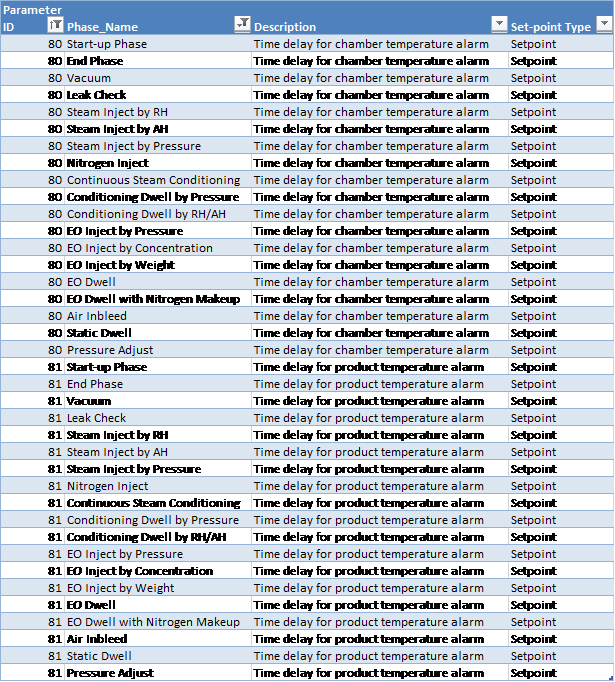
Time Delay for Chamber/Product Temperature Alarm
At the start of each phase listed below, the system will wait for the time delay to elapse before raising any chamber/product temperature alarms.
The following phases support this feature:
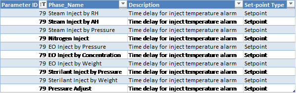
Time Delay for Inject Temperature Alarm
When the inject temperature goes outside the allowed alarm tolerance, the system will wait this long before raising the inject temperature alarm.
The following phases support this feature:
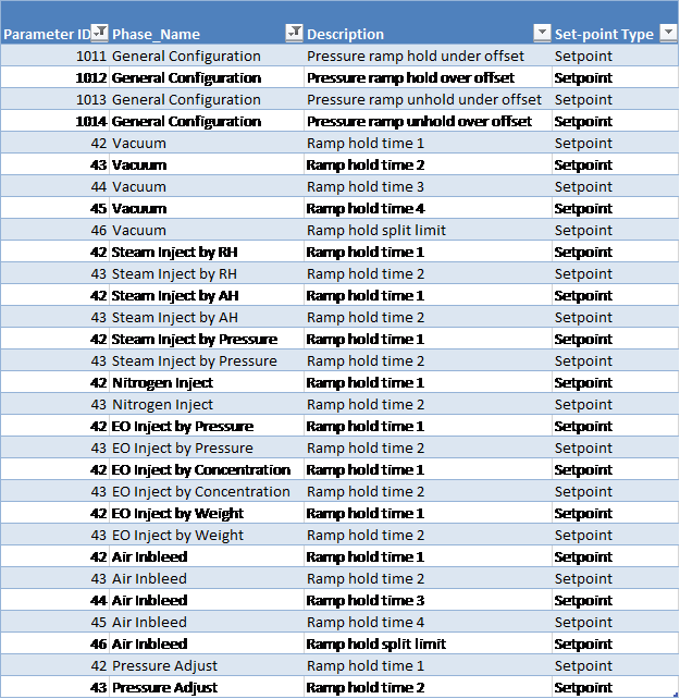
Ramp-Hold Time Parameters
Ramp hold time parameters are used to detect issues during inject or vacuum. A ramp hold is designed to detect a chamber not achieving pressure ramp. Pressure ramp is calculated in the PLC based on the specified pressure increment (parameter 18) and duration interval (parameter 19).
The ramp hold timer accumulates when the chamber is in Run mode, in a ramp-type phase (vacuum or inject), and the measured controlling pressure lags behind the calculated pressure ramp by more than a configured offset.
The ramp hold timer resets when the pressure no longer lags behind the pressure ramp, or when the chamber is not in Run mode and Ramp Hold Time 2 is exceeded.
If a Vacuum template is used with a start-up sequence, ramp hold time will only start accumulating after the start-up sequence completes.
The pressure ramp is the absolute pressure set-point continually calculated by the system during an inject/vacuum phase based on the programmed pressure rate.
The pressure ramp is considered to be on hold as follows:
-
Pressure ramp hold under offset [Parameter 1011]: ramp set-point minus this offset defines the minimum pressure value at which ramp hold occurs (i.e. if the measured pressure drops below this value, ramp hold will occur).
-
Pressure ramp hold over offset [Parameter 1012]: ramp set-point plus this offset defines the maximum pressure value at which ramp hold occurs (i.e. if the measured pressure is above this value, ramp hold will occur).
-
Pressure ramp un-hold under offset [Parameter 1013]: ramp set-point minus this offset defines the minimum pressure value at which ramp un-hold occurs (i.e. if the measured pressure is above this value, ramp hold will reset). The un-hold offset should be less than the hold offset.
-
Pressure ramp un-hold over offset [Parameter 1014]: ramp set-point minus this offset defines the maximum pressure value at which ramp un-hold occurs (i.e. if the measured pressure is below this value, ramp hold will reset). The un-hold offset should be less than the hold offset.
When a ramp hold occurs, the system will raise ramp hold alarms after a time delay expires, as described below.
The following types of ramp-hold alarms can be raised by the system while a ramp is on hold:
-
Type 1: raised after Ramp hold time 1 elapses
-
Type 2: raised after Ramp hold time 2 elapses (configured by default to put the chamber on Hold)
-
Type 3 (Air In-bleed and Vacuum phases only): raised after Ramp hold time 3 elapses
-
Type 4 (Air In-bleed and Vacuum phases only): raised after Ramp hold time 4 elapses (configured by default to put the chamber on Hold)
Note that each of the listed phases has one pair of Type 1 and Type 2 ramp-hold time set-points except for the Vacuum and Air subsystems which also have Type 3 and Type 4 ramp-hold time set-points:
-
Air In-bleed phase: Type 1 and Type 2 set-points are used when the pressure is below the Air In-bleed ramp hold split limit [Parameter 46]
-
Air In-bleed phase: Type 3 and Type 4 set-points are used when the pressure is above the Air In-bleed ramp hold split limit [Parameter 46]
-
Vacuum phase: Type 1 and Type 2 set-points are used when the pressure is above the Vacuum ramp hold split limit [Parameter 46]
-
Vacuum phase: Type 3 and Type 4 set-points are used when the pressure is below the Vacuum ramp hold split limit [Parameter 46]
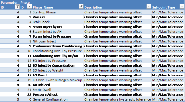
Hysteresis Tolerance Parameters and Warning Alarms
-
Minimum Hysteresis Tolerance: clears the “alarm low” condition when the measured value rises above the alarm value by the hysteresis amount.
-
Maximum Hysteresis Tolerance: clears the “alarm high” condition when the measured value falls below the alarm value by the hysteresis amount.
-
Maximum warning alarm is raised when the measured value rises above the maximum alarm minus the warning offset.
-
This warning alarm is cleared when the measured value drops below the maximum alarm minus the offset minus hysteresis amount.
-
-
Minimum warning alarm is raised when the measured value drops below the minimum alarm plus the warning offset.
-
This warning alarm is cleared when the measured value rises above the minimum alarm plus the offset plus hysteresis amount.
-
The following subsections describe which warning alarms are available for what phases.
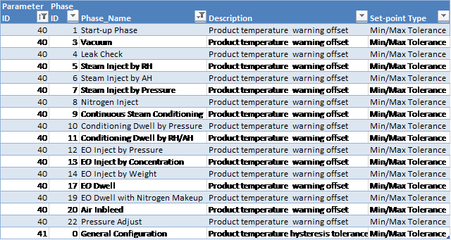
Chamber Temperature
The following phases support chamber temperature warnings:
Jacket Temperature
The following phases support jacket temperature warnings:

Product Temperature
The following phases support product temperature warnings:
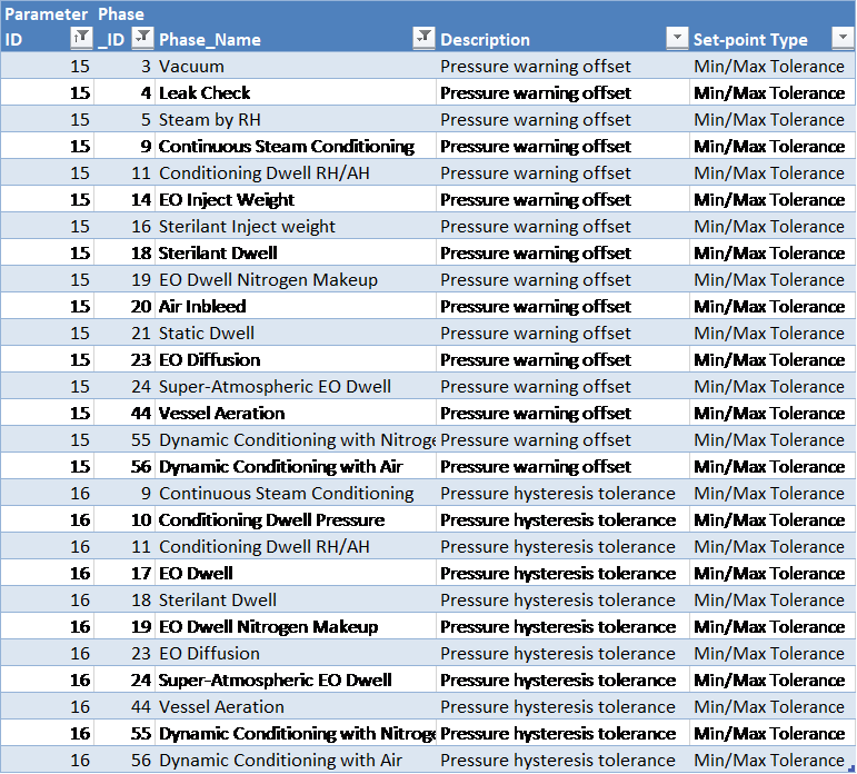
Pressure
The following phases support pressure warnings:
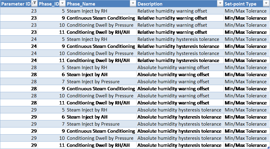
Relative and Absolute Humidity
The following phases support warning alarms for relative and absolute humidity:
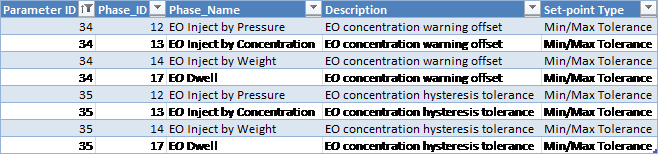
EO Concentration
The following phases support EO concentration warnings:
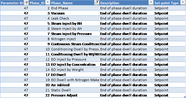
End of Phase Dwell Durations
When phase completion criteria are satisfied, the system will wait the amount configured in Parameter 47 for the phase before advancing to the next phase.
Note: If you set Parameter 47 to zero (0), the actual value that is sent to the PLC will be 5 seconds. The system cannot accept a value of zero for this parameter.
The following phases support this feature:
Offsets for Phase End
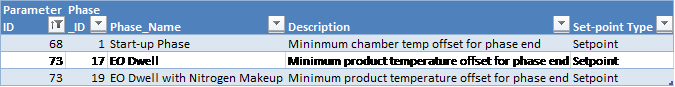
Chamber and Product Temperature
-
Start-up phase minimum chamber temperature offset for phase end [Parameter 68]: the chamber temperature must be above the minimum allowed tolerance plus this offset value in order for the phase to complete.
-
Minimum product temperature offset for phase end [Parameter 73]: defines the product temperature offset from the minimum allowed tolerance that must be achieved in order for the phase to complete. This value may be set to zero.
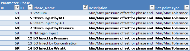
Pressure
-
Minimum pressure offset for phase end: defines the pressure offset from the minimum allowed tolerance that must be achieved in order for the phase to complete. This value may be set to zero.
-
Maximum pressure offset for phase end: defines the pressure offset from the maximum allowed tolerance that must be achieved in order for the phase to complete. This value may be set to zero.
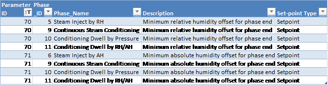
Relative/Absolute Humidity
Relative/Absolute Humidity phase end offset
-
Minimum relative/absolute humidity offset for phase end: defines the relative/absolute humidity offset from the minimum allowed tolerance that must be achieved in order for the phase to complete. This value may be set to zero.
EO Concentration
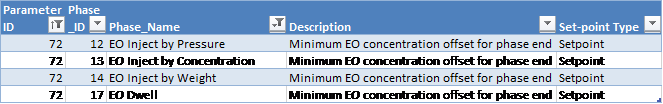
-
Minimum EO concentration offset for phase end: defines the EO concentration offset from the minimum allowed tolerance that must be achieved in order for the phase to complete. This value may be set to zero.
Run Record Inserts
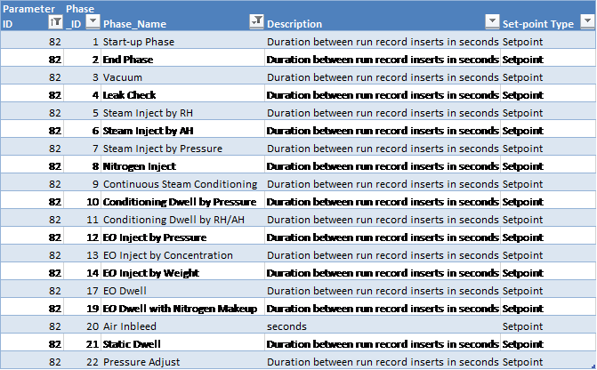
-
The duration (in seconds) between run record inserts defines the frequency with which the system will insert run record data into the database.
Cycle Execution Options
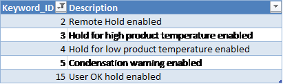
The following cycle execution options are available for all phases:
-
Remote Hold Enabled [Keyword 2]: configured on a per-phase basis in Equipment/Phase chamber configuration only (except General Configuration, Loop, Air Wash Loop, Nitrogen Wash Loop, and Steam Conditioning Loop). See section Common Subsystems for more information on the functionality of remote hold enabled.
-
Hold for low/high product temperature enabled [Keywords 3 and 4]: the system will place the chamber on Hold if the product temperature is too low/high.
-
Condensation warning/alarm enabled [Keyword 5]: at the beginning of steam phases, the steam pressure set-point is set to the value from the cycle definition, the current value of the EO partial pressure is stored, and the partial pressure of steam is changed to be the same as the pressure in the chamber in order to calculate condensation warnings and alarms:
-
RH Sensor is enabled:
-
Relative humidity (RH) will be calculated using the jacket temperature and the measured water vapour density
-
If the resultant RH is 99.5% or higher, an alarm will be raised
-
-
RH Sensor is disabled:
-
Using the jacket temperature, saturated steam partial pressure will be looked up using the steam table
-
If the resultant partial pressure is lower than the estimated partial pressure of steam in the chamber, an alarm will be raised
-
-
When the jacket temperature is lower than the chamber temperature by the “condensation warning offset” amount (a configurable parameter, see section Miscellaneous General Configuration Parameters), an alarm will be raised
-
Condensation warning algorithm will be working with a smaller partial pressure of steam after dynamic phases resulting in a reduced probability of a warning being raised if the RH sensor is disabled.
-
-
User OK Hold Enabled [Keyword 15]: configured on a per-phase basis in Equipment/Phase chamber configuration only (except General Configuration, Loop, Air Wash Loop, Nitrogen Wash Loop, and Steam Conditioning Loop). See section User OK for more information on the functionality, User OK Hold Enabled.
Equipment/Phase Chamber Configuration and Transferring Loads
The following chamber configuration functionality is available:
-
Equipment/Phase Chamber Configuration approval:
-
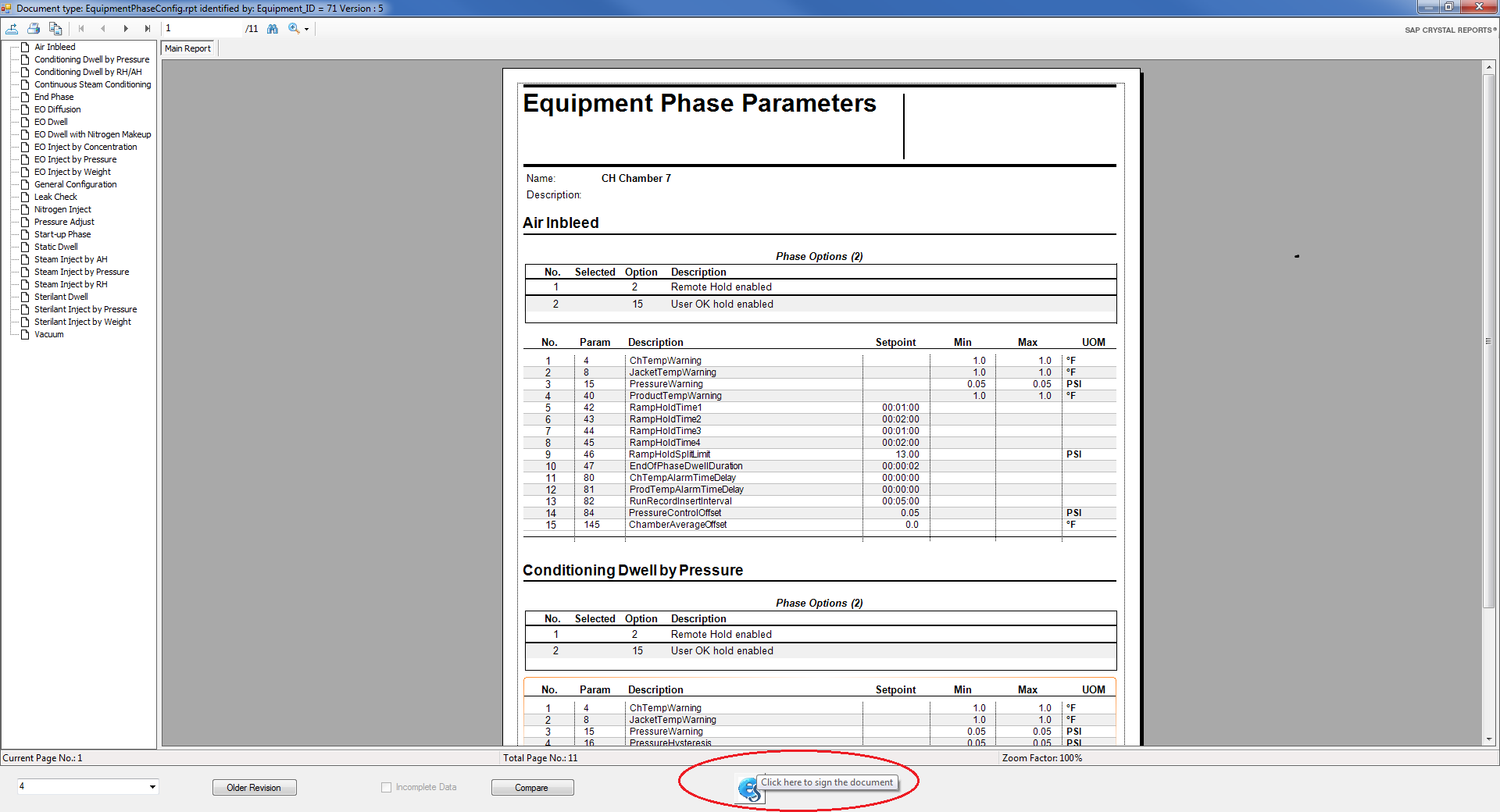
Chamber Configuration can be approved by electronically signing the Equipment Phase Configuration report. Click the “Preview/Sign” button to view and sign this report:
-
Clicking the Preview/Sign button will display the Equipment Phase Parameters report. To sign the report, click the
 button at the bottom of the display
 Note: Only users with the role “Chamber Configuration Approver” will be able to electronically sign the Equipment/Phase Configuration report.
-
A PDF of each electronically approved Equipment/Phase Configuration report will be saved.
-
If a new version of the same document is electronically approved, a new PDF file will be created.
-
Users are able to retrieve the old version and compare it to the new version of the document.
-
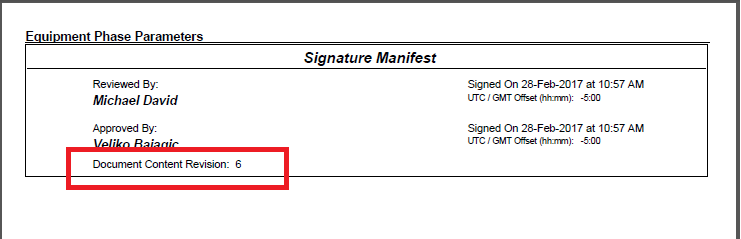
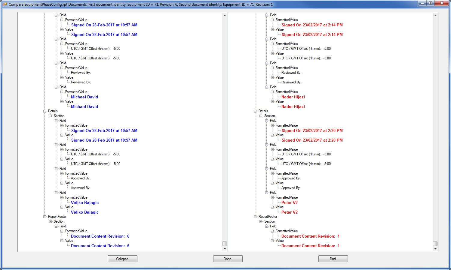
The document content revision number is shown on the last page of the report within the Signature Manifest:
-
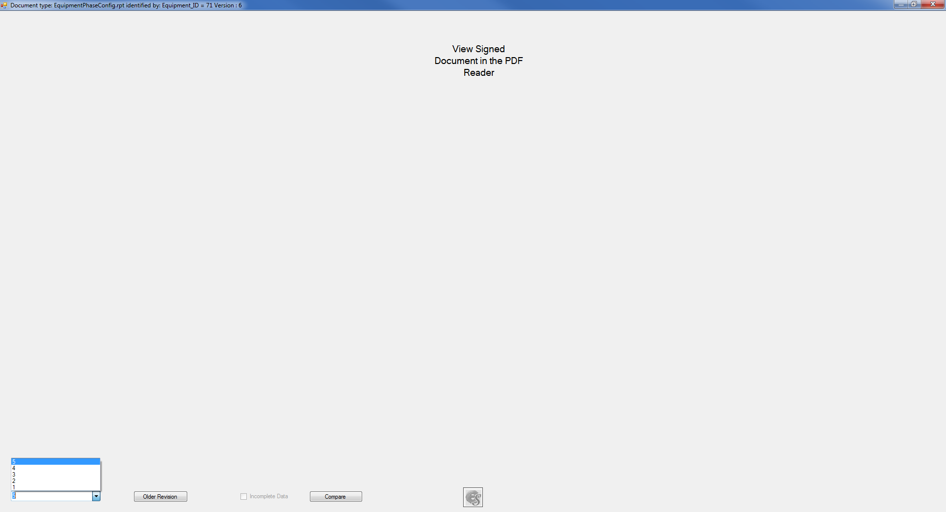
Older revisions of the report are available in the application or when previewing where a drop-down with older revision numbers allows the selection of previously signed reports.
-
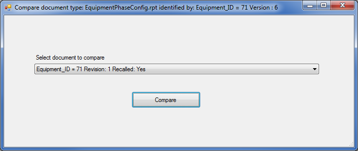
Click the Compare button and then select the document to compare.
-
A comparison of the two document versions will be presented.
-
-
Transferring Loads to the Process Controller:
-
Transferring a load to the PLC will fail if the chamber configuration is not approved unless the user-interface option “Allow load transfer with pending chamber configuration” is set.
-
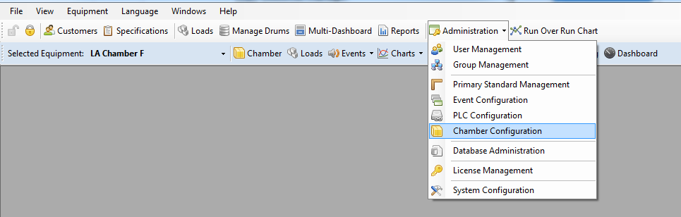
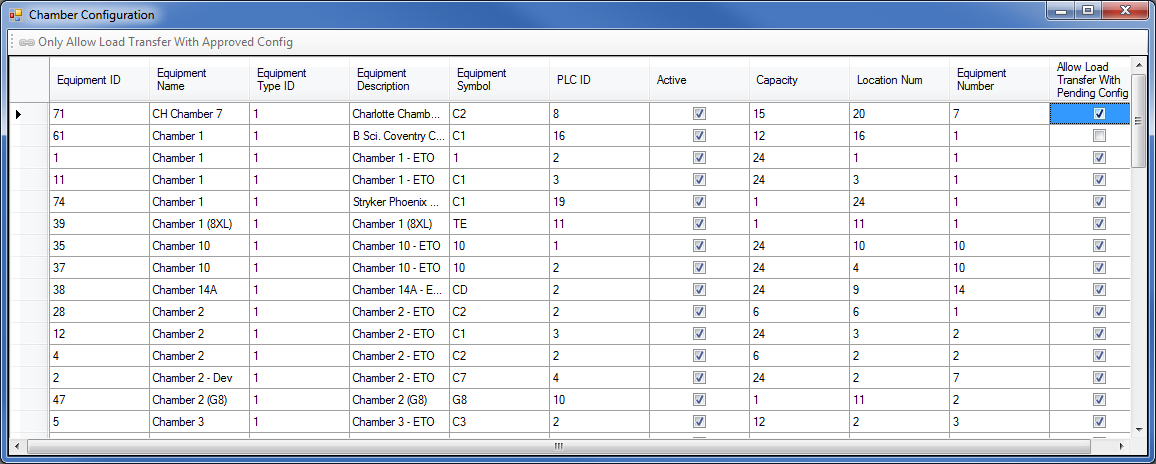
To set the “Allow load transfer with pending chamber configuration” option, select the “Chamber Configuration” screen from the Administration drop-down menu.
-
Click the check box for the desired chamber to set the option to true.
-
Only users with the role “Allow running loads with pending chamber configuration” will be able to configure the user-interface option “Allow load transfer with pending chamber configuration”.
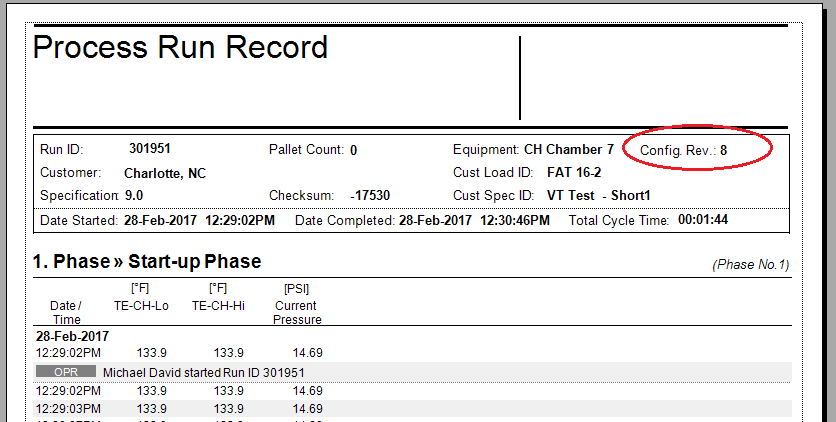
Note: If the chamber is configured with “Allow Load Transfer With Pending Config” option as TRUE, the Run Records will show Pending equipment configuration regardless of whether the Equipment/Phase Configuration is approved.
-
-
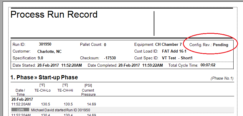
Run Record:
-
The Run Record report will indicate the version of the Equipment/Phase Configuration that was approved when the load was transferred to the PLC.
-
If the load was transferred without approved chamber configuration, the Run Record report will indicate that the Equipment/Phase Configuration was Pending for this load.
-
Running Loads with Pending Configuration
When a Chamber Configuration is approved, you can still run loads under a pending test configuration and then revert to the previously signed/approved configuration. This can be achieved as follows:
-
Electronically sign the Equipment/Phase Configuration report in order to approve the current chamber configuration.
-
Export the chamber configuration into an xml file.
-
Make changes to the approved chamber configuration by editing the parameter values or keyword options.
-
Attempting to transfer a load at this point would fail due to chamber configuration not being approved; system will detect that it has changed since last approval.
-
-
In order to run a load with the unapproved/test configuration, set the user-interface option “Allow running loads with pending chamber configuration” to TRUE and then transfer the load to the PLC.
-
After the load is complete, revert the chamber configuration to the original approved settings. This can be done by manually reverting the parameter values and keyword options or simply by importing the configuration xml file that was exported after the chamber configuration was approved.
-
Note that reverting the chamber configuration to the original will NOT require applying a new e-signature
-
-
Uncheck the user-interface option “Allow running loads with pending chamber configuration” and transfer a load to the PLC.
-
System will detect that the chamber configuration is the same as when it was last approved and will allow the transfer to take place.
-
In-Spec Timer Rules
During certain phases, the system uses an in-spec timer which only accumulates under specific conditions. The in-spec timer is used to satisfy completion criteria for some phases (see section Supported Phases on supported phases for more information).
The table below summarizes the conditions which will cause the in-spec timer to hold during various phases.
|
In-spec Timer Hold Condition |
Phases |
|---|---|
|
Hold mode |
Continuous Steam Conditioning Dynamic Conditioning with Nitrogen Dynamic Conditioning with Air Vacuum |
|
When chamber temperature (either average or minimum of the chamber thermocouples as per setting of keyword 22) is less than the phase minimum tolerance (parameter 3), the in-spec timer turns off. When the temperature rises above the minimum phase tolerance plus the minimum hysteresis tolerance (parameter 5), the in-spec timer will turn on. |
Conditioning Dwell Pressure Conditioning Dwell RH Dynamic Conditioning with Nitrogen Dynamic Conditioning with Air Continuous Steam Conditioning Static Dwell EO Dwell EO Dwell Nitrogen Makeup Super Atmospheric EO Dwell |
|
When chamber RH (measured or calculated from AH) is less than the phase minimum tolerance (parameter 22), the in-spec timer turns off. When RH rises above the minimum phase tolerance plus the minimum hysteresis tolerance (parameter 24), the in-spec timer will turn on. |
Conditioning Dwell Pressure Conditioning Dwell RH EO Dwell EO Dwell Nitrogen Makeup Super Atmospheric EO Dwell |
|
When product temperature is less than the phase minimum tolerance (parameter 39), the in-spec timer turns off. When product temperature rises above the minimum phase tolerance plus the minimum hysteresis tolerance (parameter 41), the in-spec timer will turn on. |
EO Dwell EO Dwell Nitrogen Makeup Super Atmospheric EO Dwell |
|
When measured EO concentration is less than the phase minimum tolerance (parameter 33), the in-spec timer turns off. When the measured EO concentration rises above the minimum phase tolerance plus the minimum hysteresis tolerance (parameter 35), the in-spec timer will turn on. |
EO Dwell EO Dwell Nitrogen Makeup Super Atmospheric EO Dwell |
|
Stop Mode |
All phases |
|
When chamber pressure is less than the phase minimum tolerance (parameter 78), the in-spec timer turns off. When the pressure rises above the minimum phase tolerance plus the minimum hysteresis tolerance (parameter 16), the in-spec timer will turn on. |
EO Dwell EO Dwell Nitrogen Makeup Super Atmospheric EO Dwell |
Automatic PLC Configuration Recovery
The automatic PLC configuration recovery function will perform the following:
-
Detect if a PLC is ready or not. If not ready:
-
Do not process buffers
-
Do not capture analog data
-
Display service sends error to all clients – “Process Control Module is not configured. Please contact your system administrator.”
-
-
Ensure that the watchdog timer is working. No recovery process will commence unless the watchdog in the PLC is operating
-
If PLC is ready, then one of the services will perform the following:
-
Write PLC configuration data
-
Write PLC State data
-
Write event configuration data
-
If a cycle in the PLC was completed, write the last recipe into the PLC
-
-
When PLC detects that its configuration has been updated, it will:
-
Start running its complete program
-
Resume from the beginning or from the middle of the last phase as restored by the state
-
Place all equipment in Stop mode
-
-
After PLC configuration has been restored, the services will commence normal operation