Supported Phases
Overview
Chamber temperature and jacket temperature will be controlled during all phases unless the chamber enters Stop mode.
Each phase will have a pre-defined phase start and end conditions that will consist of combination of measured process parameters and meeting minimum in-specification phase duration.
The controller will not latch phase end conditions unless the chamber is in the Run mode: this is to avoid placing the chamber on Hold after phase end criteria were reached but before the phase transitions.
The subsections below include all phases supported by the system and include, for each phase, information related to the following:
-
Active Subsystems
-
Process description (if applicable)
-
Chamber Configurable Parameters (if applicable)
-
Operational Parameters
-
Customer Parameters
-
Periodically Reported Device Measurements
-
Device Measurements Summary
-
Phase Completion criteria.
Note that certain Parameters can be modified during the phase as described in section Manual Overrides.
Note: Your site must have the appropriate I/O configuration in order to facilitate the use of certain parameters listed in this section. Please refer to your site’s System Functional Specification document(s) to see a list of supported phases, parameters, and associated I/O configuration.
General Configuration (Header)
The general configuration assigned in the header will apply throughout the cycle.
Operational Parameters
Customer Operational Options
Process
-
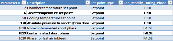
System will heat and cool the chamber according to dormant temperature parameters 58 (cooling set-point), 2 (chamber temperature set-point), and 6 (jacket temperature set-point) as described in section Chamber Heating/Cooling Control.
-
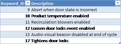
Abort when door state is incorrect [Keyword 9]: if this option is enabled, the cycle will be aborted if the door enters a faulted state.
-
Product temperature monitoring enabled [Keyword 10]: the system will monitor product temperature throughout the entire cycle – alarms related to product temperature will be active.
-
Re-circulation blowers enabled [Keyword 11]: the system will run the recirculation blowers throughout the entire cycle (except in Stopped mode).
-
Loosen door locks [Keyword 12]: system will raise an event to let operator know when to loosen door locks (occurs at start of final Air In-bleed phase).
-
Audio-visual beacon disabled at end of cycle [Keyword 13]:
-
If this keyword is set, the system will raise Alarm 149 when the cycle reaches the End Phase. This event is NOT configured to trigger the audio/visual beacon by default.
-
If this keyword is NOT set, the system will raise Alarm 231 when the cycle reaches the End Phase. This event is configured to trigger the audio/visual beacon by default.
-
-
Tighten door locks [Keyword 17]: the system will raise an event to let operator know when to tighten door locks during first Vacuum phase (occurs at 95 kPa).
-
If tighten door locks pressure parameter 178 is configured, the Tighten Door Locks event will be raised when pressure drops below this pressure regardless of the state of the Tightens Door Locks Keyword 17
-
-
Non-EO abort phase is determined at time of recipe creation as follows:
-
If System Configuration Parameter “Abort1_Use_Vac_Before_FINAL_Air” is set to TRUE see System Configuration Form, the cycle execution engine will jump to the Vacuum phase that occurs before the final Air In-bleed phase in the cycle.
-
If System Configuration Parameter, see System Configuration Form, “Abort1_Use_Vac_Before_FINAL_Air” is set to FALSE, the cycle execution engine will jump to the first Vacuum phase in the final air wash sequence of the cycle definition.
-
The default value of System configuration parameter “Abort1_Use_Vac_Before_FINAL_Air” is FALSE. This is a non-managed parameter that can only be set by the database administrator.
-
-
The EO abort phase is determined at time of recipe creation and is the first Vacuum phase after the last EO Dwell (or EO Inject if no EO Dwell exists).
-
The phase for last Air In-bleed is defined as the final Air In-bleed phase of the cycle.
-
While the chamber is in Dormant sequence, the system will maintain the jacket and chamber temperatures using the jacket temperature and chamber temperature set-point parameters.
Start-up
In this phase the control system checks several parameters related to utilities and chamber temperature.
Active Subsystems
The following subsystems are active during this process phase:
-
Chamber Heat
-
If the blower option is selected, then subsystem recirculation blowers is active as well.
Operational Parameters
Customer Parameters
Phase Completion
The phase is completed when the following conditions are satisfied
-
Chamber air temperature is within specifications.
-
If multiple chamber temperature thermocouples are configured, then the lowest chamber temperature reading must be greater than or equal to the minimum temperature tolerance (plus the offset for phase end parameter 68) in order for this phase completion criterion to be satisfied
-
-
Jacket temperature is within specifications.
-
Pressure sensors are operational
-
If product temperature monitoring is enabled, product temperature sensors are operational
-
EO temperature monitoring is operational.
-
If enabled for the cycle, recirculation blowers are operational. Note: if blower feedback delay is set to 0 seconds start-up phase completion will be prevented; this is to avoid accidentally running a cycle without blower alarms being raised.
-
Door(s) closed.
Periodically Reported Device Measurements
The following information is periodically reported throughout the phase. The duration between each record insert is defined in section Run Record Inserts of the chamber configuration parameters.
-
Time
-
Pressure
-
Pressure Set-point
-
Lowest and Highest Chamber Temperature
Device Measurements Summary
If enabled for your site, the following information will be reported in the phase summary. Otherwise no parameters are reported in the summary for this phase.
-
Final Lowest Chamber Temperature
-
Final Highest Chamber Temperature
If any of the above device measurements fall outside of specified alarm tolerances, a deviation will be indicated on the report.
Vacuum
Removes chamber gas at a prescribed rate to an absolute or a relative pressure set-point.
Duration Set-point [Operational Parameter 10] will be available in the Vacuum Phase when Pressure Monitoring Template PMT4 is in use. As a result, an additional completion criterion will be applicable.
Note: The interlock conditions described in section Phase Start Interlocks for this phase must be met before it is allowed to start.
Active Subsystems
The following subsystems are active during this process phase:
-
Chamber Heat
-
Vacuum
-
If the blower option is selected, then subsystem Re-circulation Blowers is active as well.
-
If the product temperature option was selected, then subsystem Product Temperature Monitoring is active as well.
Process
-
Vacuum hold duration:
-
When the pressure is less than or equal to the set-point (parameter 12), and if parameter 49 was set to a value greater than zero, the system will raise Alarm 361 ("Vacuum Hold has started") and will enter a dwell period during which it will wait for the time set by the vacuum hold duration parameter 49 to elapse. Main vacuum valve will stay closed during this time.
-
If the pressure at the end of the vacuum hold period has risen above the Vacuum phase pressure set-point (parameter 12), a re-evacuation will occur: the vacuum subsystem will remove the additional gas from the chamber until the pressure is less than or equal to the pressure set-point.
-
After the re-evacuation completes, the system will advance to the next phase.
-
If during the vacuum hold dwell period or during the re-evacuation segment the total Vacuum phase duration exceeds the maximum duration tolerance (parameter 11 Max) less 1 minute (and pressure is less than the maximum tolerance parameter 14), or the pressure drops so that it is less than or equal to the minimum tolerance parameter 14, the vacuum hold dwell period or re-evacuation will be interrupted and the phase will be allowed to advance.
-
-
Pressure increment for specified duration (parameter 18): defines how much the pressure should change during the specified duration interval (parameter 19, in seconds).
-
If the pressure changes by more than the “pressure change alarm tolerance” parameter during the specified duration for pressure increment, an alarm is raised and chamber goes on Hold.
-
High Concentration End Limit: estimated and, if available, measured EO concentration falls below this level, the emission control output is turned off.
-
When the “Gas valve boil off duration” [Phase Parameter 98] is set, the following conditions apply:
-
If the current phase is Vacuum and it has a boil-off duration set greater than zero (0) then the gas valve(s) will stay open for the Vacuum phase boil-off duration, timing from the beginning of the Vacuum phase.
-
If the boil-off period started in a previous phase, then the boil-off will use the duration from the previous phase's Parameter 98, unless the current phase is Vacuum or Nitrogen Inject.
-
If the Vacuum phase completes before the boil-off duration has expired, the boil-off time will also expire.
-
If chamber enters Hold or Stop mode during a boil-off, then the gas valve(s) will close and the Gas Valve Boil-Off Duration [Phase Parameter 98] will be paused. The boil-off will resume for the remainder of the Gas Valve Boil-Off Duration when the chamber is put back in Run.
-
Boil-off will only be allowed during Normal cycle sequence.
-
-
Vacuum pump(s) operation:
-
After the Vacuum phase completes, the system will keep the vacuum pump(s) running for the “vacuum pump off-delay” duration [Parameter 1023], if the parameter is set.
-
If configured for your chamber, the vacuum pump(s) will continue to run for the duration of the Vacuum phase “end of phase dwell duration” [Equipment/Phase Parameter 47], or 10 seconds, whichever is greater, whenever the chamber goes into Hold or at the end of the Vacuum phase.
-
This configuration will NOT override any explicit vacuum pump stopping sequence that may be defined in the Vacuum Template VT#.
-
-
Chamber Configurable Parameters

Operational Parameters
Customer Parameters
Periodically Reported Device Measurements
The following information is periodically reported throughout the phase. The duration between each record insert is defined in section Run Record Inserts of the chamber configuration parameters.
-
Time
-
Pressure
-
Pressure Set-point
-
Lowest and Highest Chamber Temperature
-
Product temperature
Device Measurements Summary
The following information will be reported in the phase summary:
-
Phase Duration:
-
In-Spec Time (deviation raised if less than Minimum Duration Tolerance Parameter 11 Min).
-
Total Phase Time (deviation raised if exceeds Maximum Duration Tolerance Parameter 11 Max).
-
-
Final Pressure
-
Minimum Chamber Temperature
-
Maximum Chamber Temperature
-
Minimum Product Temperature
-
Maximum Product Temperature
If any of the above device measurements fall outside of specified alarm tolerances, a deviation will be indicated on the report.
Phase Completion
The phase is completed when one of the following is true.
-
Pressure is less than or equal to the set-point (parameter 12) and elapsed phase time is greater than or equal to the minimum duration tolerance (parameter 11 Min) and vacuum hold duration (parameter 49) has elapsed.
-
If Duration Set-point is available: Pressure is less than or equal to the maximum tolerance (parameter 14 Max) minus the equipment/phase offset parameter 69 and elapsed in-spec phase time is greater than or equal to the duration set-point [Parameter 10]
-
Pressure is less than or equal to the maximum tolerance (parameter 14 Max) minus the equipment/phase offset parameter 69 and elapsed phase time is greater than or equal to the maximum duration tolerance (parameter 11 Max) less 1 minute.
-
Pressure is less than or equal to the minimum pressure alarm tolerance (parameter 14 Min).
Leak Check
The leak check is a dwell phase during which pressure is checked for a period of time.
Active Subsystems
The following subsystems are active during this process phase:
-
Chamber Heat
-
Vacuum
-
If the blower option is selected, then subsystem Re-circulation Blowers is active as well.
-
If the product temperature option was selected, then subsystem Product Temperature Monitoring is active as well.
Process
-
The system uses the value of parameter 12 as the pressure set-point.
-
If the pressure set-point parameter 12 is set to zero (or not configured), the system will use the final pressure from the previous phase as the pressure set-point.
-
Alarm 360: Leak Check Vacuum has completed, leak check timer has reset: the system will raise an event when the phase in-spec time is reset after the pressure has been corrected due to rising above the pressure set-point plus control offset Parameter 260 (or parameter 84 in older PLC Module versions before version 31).
-
Leak Check pressure control offset defines the amount by which the pressure is allowed to deviate from the set-point during the Leak Check phase before the system raises an alarm.
-
If the pressure does not rise above the set-point plus offset parameter 260, leak check will have passed.
-
If the pressure rises above the set-point plus offset parameter 260, an alarm is raised and the vacuum subsystem is turned on until the pressure is less than or equal to the pressure set-point.
-
The cycle is automatically aborted if the pressure rises above the set-point plus offset parameter 260 three times.
-
Pressure increment for specified duration (parameter 18): defines how much the pressure should change during the specified duration interval (parameter 19, in seconds).
Operational Parameters
Customer Parameters
Periodically Reported Device Measurements
The following information is periodically reported throughout the phase. The duration between each record insert is defined in section Run Record Inserts of the chamber configuration parameters.
-
Time
-
Pressure
-
Pressure Set-point
-
Lowest and Highest Chamber Temperature
-
Product temperature
Device Measurements Summary
The following information will be reported in the phase summary:
-
Phase Duration:
-
In-Spec Time (deviation raised if less than Minimum Duration Tolerance Parameter 11 Min).
-
Total Phase Time (deviation raised if exceeds Maximum Duration Tolerance Parameter 11 Max).
-
-
Minimum Pressure
-
Maximum Pressure
-
Minimum Chamber Temperature
-
Maximum Chamber Temperature
-
Minimum Product Temperature
-
Maximum Product Temperature
If any of the above device measurements fall outside of specified alarm tolerances, a deviation will be indicated on the report.
Phase Completion
The phase is completed when the In-Spec time is greater than or equal to the duration set-point (parameter 10). See section In-Spec Timer Rules for more information.
Static Dwell
Static Dwell is used to soak product for a period of time with the gas that was injected in the previous phase. This phase will:
-
Maintain current temperature for a duration of time
-
Disallow any inject or vacuum
Active Subsystems
The following subsystems are active during this process phase:
-
Chamber Heat
-
If the blower option is selected, then subsystem Re-circulation Blowers is active as well.
-
If the product temperature option was selected, then subsystem Product Temperature Monitoring is active as well.
Operational Parameters
Customer Parameters
Periodically Reported Device Measurements
The following information is periodically reported throughout the phase. The duration between each record insert is defined in section Run Record Inserts of the chamber configuration parameters.
-
Time
-
Pressure
-
Pressure Set-point
-
Lowest and Highest Chamber Temperature
-
Product Temperature
Device Measurements Summary
The following information will be reported in the phase summary:
-
Phase Duration:
-
In-Spec Time (deviation raised if less than Minimum Duration Tolerance Parameter 11 Min).
-
Total Phase Time (deviation raised if exceeds Maximum Duration Tolerance Parameter 11 Max).
-
-
Minimum Pressure
-
Maximum Pressure
-
Minimum Chamber Temperature
-
Maximum Chamber Temperature
-
Minimum Product Temperature
-
Maximum Product Temperature
If any of the above device measurements fall outside of specified alarm tolerances, a deviation will be indicated on the report.
Phase Completion
The phase is completed when one of the following is true.
-
In-spec. time is greater than or equal to the duration set-point (parameter 10).
-
In-spec. time is greater than or equal to the duration minimum tolerance (parameter 11 Min) and total time elapsed is greater than or equal to the duration maximum tolerance (parameter 11 Max) less 1 minute.
-
If the optional product temperature set-point is specified then the lowest product temperature is greater than or equal to the product temperature set-point (parameter 100) and in-spec. time is greater than or equal to the duration minimum tolerance (parameter 11 Min).
See section In-Spec Timer Rules for more information on In-Spec Timer rules.
Pressure Adjust
Active Subsystems
The following subsystems are active during this process phase:
-
Chamber Heat
-
Vacuum
-
Nitrogen
-
If the blower option is selected, then subsystem Re-circulation Blowers is active as well.
-
If the product temperature option was selected, then subsystem Product Temperature Monitoring is active as well.
Process
The chamber pressure will be adjusted to the set-point from specification:
-
If the pressure is higher than the pressure set-point plus the “pressure control offset” (parameter 84), the vacuum subsystem turns on until chamber pressure is within pressure set-point plus the offset.
-
If the pressure is lower than the pressure set-point minus the “pressure control offset” (parameter 84), the nitrogen subsystem turns on until the chamber pressure is within pressure set-point minus the offset.
-
If the “pressure control offset” (parameter 84) is not set, or is set to less than 1 mbar, the process control module will take its value to be 1 mbar.
-
Pressure increment for specified duration (parameter 18): defines how much the pressure should change during the specified duration interval (parameter 19, in seconds).
-
If the pressure changes by more than the “pressure change alarm tolerance” parameter during the specified duration for pressure increment, an alarm is raised and chamber goes on Hold.
Chamber Configurable Parameters

Operational Parameters
Customer Parameters
Periodically Reported Device Measurements
The following information is periodically reported throughout the phase. The duration between each record insert is defined in section Run Record Inserts of the chamber configuration parameters.
-
Time
-
Pressure
-
Pressure Set-point
-
Lowest and Highest Chamber Temperature
-
Product temperature
Device Measurements Summary
The following information will be reported in the phase summary:
-
Phase Duration:
-
In-Spec Time (deviation raised if less than Minimum Duration Tolerance Parameter 11 Min)
-
Total Phase Time (deviation raised if exceeds Maximum Duration Tolerance Parameter 11 Max)
-
-
Final Pressure
-
Minimum Chamber Temperature
-
Maximum Chamber Temperature
-
Minimum Product Temperature
-
Maximum Product Temperature
If any of the above device measurements fall outside of specified alarm tolerances, a deviation will be indicated on the report.
Phase Completion
The phase is completed when chamber pressure is within pressure set-point (parameter 12) plus or minus the “pressure control offset” parameter 84 value.
Conditioning Dwell via Pressure
The system holds current chamber environmental conditions for a period of time and makes-up steam under certain conditions.
Note: The interlock conditions described in section Phase Start Interlocks for this phase must be met before it is allowed to start.
Active Subsystems
The following subsystems are active during this process phase:
-
Chamber Heat
-
Humidity Monitoring
-
Steam
-
If the blower option is selected, then subsystem Re-circulation Blowers is active as well.
-
If the product temperature option was selected, then subsystem Product Temperature Monitoring is active as well.
Process
Pressure is monitored and steam is made-up (i.e. system adds steam until the pressure is greater than or equal to the set-point) under the following condition: chamber pressure falls below the pressure set-point minus the pressure control differential (parameter 86) value.
-
If ConfigParameter ShowFinalHumidityForSteamPhases is set to TRUE:
-
Final %RH and Final AH (instead of minimum/maximum) will be reported in the phase summary and a deviation will be raised if the Final %RH and/or Final AH (instead of minimum/maximum) is outside the associated phase tolerance.
-
Chamber Configurable Parameters

Operational Parameters
Customer Parameters
Periodically Reported Device Measurements
The following information is periodically reported throughout the phase. The duration between each record insert is defined in section Run Record Inserts of the chamber configuration parameters.
-
Time
-
Pressure
-
Pressure Set-point
-
Lowest and Highest Chamber Temperature
-
Product temperature
-
Relative Humidity (%RH) Device 49:
-
If RH sensor(s) is/are installed, this will show the Measured RH from the controlling sensor, OR
-
If no RH sensor is installed, this will show the %RH calculated based on the measured AH reading
-
-
AH Concentration (Device 85):
-
Depending on the configured HUT# template this is either the value measured by the Controlling AH sensor or it is the Measured Average reading from installed AH sensors)
-
Device Measurements Summary
The following information will be reported in the phase summary:
-
Phase Duration:
-
In-Spec Time (deviation raised if less than Minimum Duration Tolerance Parameter 11 Min)
-
Total Phase Time (deviation raised if exceeds Maximum Duration Tolerance Parameter 11 Max)
-
-
Minimum Pressure
-
Maximum Pressure
-
Minimum Chamber Temperature
-
Maximum Chamber Temperature
-
Minimum Relative Humidity
-
Maximum Relative Humidity
-
Minimum Absolute Humidity
-
Maximum Absolute Humidity
-
Final Minimum Product Temperature
-
Maximum Product Temperature
If any of the above device measurements fall outside of specified alarm tolerances, a deviation will be indicated on the report.
Phase Completion
The phase is completed when one of the following is true.
-
If the optional product temperature tolerance (parameter 39) is not specified, one of the following conditions has to be true:
-
In-spec time is greater than or equal to the duration set-point (parameter 10) OR
-
In-spec time is greater than or equal to the minimum duration tolerance (parameter 11 Min) and total phase-time elapsed is greater than or equal to the duration maximum tolerance (parameter 11 Max) less 1 minute.
-
-
The optional product temperature tolerance (parameter 39) is specified and the product temperature is greater than the minimum tolerance (parameter 39 Min) AND when one of the following conditions is true:
-
In-spec. time is greater than or equal to the duration set-point (parameter 10) OR
-
In-spec. time is greater than or equal to the duration minimum tolerance (parameter 11 Min) and total phase-time elapsed is greater than or equal to the duration maximum tolerance (parameter 11 Max) less 1 minute.
-
If the optional product temperature set-point (parameter 100) is specified and the product temperature is greater than or equal to the set-point (parameter 11) and in-spec. time is greater than or equal to the duration minimum tolerance (parameter 11 Min).
See section In-Spec Timer Rules for more information on In-Spec Timer rules.
Conditioning Dwell via RH/AH
The system holds current chamber environmental conditions for a period of time and makes-up steam under certain conditions.
Note: The interlock conditions described in section Phase Start Interlocks for this phase must be met before it is allowed to start.
Active Subsystems
The following subsystems are active during this process phase:
-
Chamber Heat
-
Humidity Monitoring
-
Steam
-
If the blower option is selected, then subsystem Re-circulation Blowers is active as well.
-
If the product temperature option was selected, then subsystem Product Temperature Monitoring is active as well.
Process
-
Relative and absolute humidity are monitored.
-
Steam is made-up under the following conditions:
-
Measured RH is below the relative humidity set-point (parameter 20) minus the “RH control differential” parameter 21 value and pressure is below the maximum pressure warning offset (equipment/phase parameter 69 Max).
-
Measured AH is below the absolute humidity set-point (parameter 25) minus the “AH control differential” parameter 26 value and pressure is below the maximum pressure warning offset (equipment/phase parameter 69 Max).
-
-
When steam make-up is initiated, the system will open the steam valve and inject steam until the RH or AH reaches RH/AH set-point (parameters 20 and 25), whichever is set.
-
If ConfigParameter ShowFinalHumidityForSteamPhases is set to TRUE:
-
Final %RH and Final AH (instead of minimum/maximum) will be reported in the phase summary and a deviation will be raised if the Final %RH and/or Final AH (instead of minimum/maximum) is outside the associated phase tolerance.
-
Operational Parameters
Customer Parameters
Periodically Reported Device Measurements
The following information is periodically reported throughout the phase. The duration between each record insert is defined in section Run Record Inserts of the chamber configuration parameters.
-
Time
-
Pressure
-
Pressure Set-point
-
Lowest and Highest Chamber Temperature
-
Product temperature
-
Relative Humidity (%RH) Device 49:
-
If RH sensor(s) is/are installed, this will show the Measured RH from the controlling sensor, OR
-
If no RH sensor is installed, this will show the %RH calculated based on the measured AH reading
-
-
AH Concentration (Device 85):
-
Depending on the configured HUT# template this is either the value measured by the Controlling AH sensor or it is the Measured Average reading from installed AH sensors)
-
Device Measurements Summary
The following information will be reported in the phase summary:
-
Phase Duration:
-
In-Spec Time (deviation raised if less than Minimum Duration Tolerance Parameter 11 Min)
-
Total Phase Time (deviation raised if exceeds Maximum Duration Tolerance Parameter 11 Max)
-
-
Minimum Pressure
-
Maximum Pressure
-
Minimum Chamber Temperature
-
Maximum Chamber Temperature
-
Minimum Relative Humidity
-
Maximum Relative Humidity
-
Minimum Absolute Humidity
-
Maximum Absolute Humidity
-
Final Minimum Product Temperature
-
Maximum Product Temperature
If any of the above device measurements fall outside of specified alarm tolerances, a deviation will be indicated on the report.
Phase Completion
The phase is completed when one of the following is true.
-
If the optional product temperature tolerance (parameter 39) is not specified AND when one of the following conditions is true:
-
in-spec time is greater than or equal to the duration set-point (parameter 10) OR
-
In-spec time is greater than or equal to the minimum duration tolerance (parameter 11 Min) and total phase-time elapsed is greater than or equal to the duration maximum tolerance (parameter 11 Max) less 1 minute.
-
-
The optional product temperature tolerance (parameter 39) is specified and the product temperature is greater than the minimum tolerance (parameter 39 Min) AND when one of the following conditions is true:
-
In-spec. time is greater than or equal to the duration set-point (parameter 10) OR
-
In-spec. time is greater than or equal to the duration minimum tolerance (parameter 11 Min) and total phase-time elapsed is greater than or equal to the duration maximum tolerance (parameter 11 Max) less 1 minute.
See section In-Spec Timer Rules for more information on In-Spec Timer rules.
Nitrogen Inject
The system will inject nitrogen gas until an absolute pressure set-point is met.
Active Subsystems
The following subsystems are active during this process phase:
-
Chamber Heat
-
Nitrogen
-
If the blower option is selected, then subsystem Re-circulation Blowers is active as well.
-
If the product temperature option was selected, then subsystem Product Temperature Monitoring is active as well.
Process
-
Pressure increment for specified duration (parameter 18): defines how much the pressure should change during the specified duration interval (parameter 19, in seconds).
-
If the pressure changes by more than the “pressure change alarm tolerance” parameter during the specified duration for pressure increment, an alarm is raised and chamber goes on Hold.
-
N2 inject temperature alarm minimum/maximum tolerance: alarm conditions to ensure that the N2 temperature is within an acceptable range.
Operational Parameters
Customer Parameters
Periodically Reported Device Measurements
The following information is periodically reported throughout the phase. The duration between each record insert is defined in section Run Record Inserts of the chamber configuration parameters.
-
Time
-
Pressure
-
Pressure Set-point
-
Lowest and Highest Chamber Temperature
-
Measured EO Concentration (if ShowEOConcInN2Phase parameter is configured for your site, see section System Configuration Form for more information)
-
Depending on the configured EOT# template this is either the value measured by the Controlling EO sensor or it is the Measured Average reading from installed EO sensors
-
-
Product temperature
Device Measurements Summary
The following information will be reported in the phase summary:
-
Phase Duration:
-
In-Spec Time (deviation raised if less than Minimum Duration Tolerance Parameter 11 Min).
-
Total Phase Time (deviation raised if exceeds Maximum Duration Tolerance Parameter 11 Max).
-
-
Final Pressure
-
Minimum Chamber Temperature
-
Maximum Chamber Temperature
-
Minimum Product Temperature
-
Maximum Product Temperature
If any of the above device measurements fall outside of specified alarm tolerances, a deviation will be indicated on the report.
Phase Completion
The phase is completed when one of the following is true.
-
Pressure is greater than or equal to the set-point (parameter 12) and elapsed phase time is greater than or equal to the minimum duration tolerance (parameter 11 Min).
-
Pressure is greater than or equal to the minimum tolerance (parameter 14 Min) plus the pressure offset (equipment/phase parameter 69 Min) and elapsed phase time is greater than or equal to the phase maximum duration tolerance (parameter 11 Max) less 1 minute.
-
Pressure is greater than or equal to the maximum tolerance (parameter 11 Max).
Steam Inject via Pressure
Inject steam until absolute or a relative pressure set-point is met.
Active Subsystems
The following subsystems are active during this process phase:
-
Chamber Heat
-
Steam
-
If the blower option is selected, then subsystem Re-circulation Blowers is active as well.
-
If the product temperature option was selected, then subsystem Product Temperature Monitoring is active as well.
Process
-
As per the cycle definition value-validation rules, either pressure set-point [Parameter 12] or pressure change set-point [Parameter 13] can be set for this phase.
-
If the “change in pressure set-point” [Parameter 13] is set, system will obtain the absolute pressure set-point as follows:
-
Absolute pressure set-point = value of the actual measured pressure at the start of the phase + “change in pressure set-point” parameter value.
-
-
Pressure increment for specified duration (parameter 18): defines how much the pressure should change during the specified duration interval (parameter 19, in seconds).
-
If the pressure changes by more than the “pressure change alarm tolerance” parameter during the specified duration for pressure increment, an alarm is raised and chamber goes on Hold.
-
Steam inject temperature alarm minimum/maximum tolerance: alarm conditions to ensure that the steam temperature is within an acceptable range.
-
If ConfigParameter ShowFinalHumidityForSteamPhases is set to TRUE:
-
Final %RH and Final AH (instead of minimum/maximum) will be reported in the phase summary and a deviation will be raised if the Final %RH and/or Final AH (instead of minimum/maximum) is outside the associated phase tolerance.
-
Operational Parameters
Customer Parameters
Periodically Reported Device Measurements
The following information is periodically reported throughout the phase. The duration between each record insert is defined in section Run Record Inserts of the chamber configuration parameters.
-
Time
-
Pressure
-
Pressure Set-point
-
Lowest and Highest Chamber Temperature
-
Product temperature
-
Relative Humidity (%RH) Device 49:
-
If RH sensor(s) is/are installed, this will show the Measured RH from the controlling sensor, OR
-
If no RH sensor is installed, this will show the %RH calculated based on the measured AH reading
-
-
AH Concentration (Device 85):
-
Depending on the configured HUT# template this is either the value measured by the Controlling AH sensor or it is the Measured Average reading from installed AH sensors)
-
Device Measurements Summary
The following information will be reported in the phase summary:
-
Phase Duration:
-
In-Spec Time (deviation raised if less than Minimum Duration Tolerance Parameter 11 Min).
-
Total Phase Time (deviation raised if exceeds Maximum Duration Tolerance Parameter 11 Max).
-
-
Final Pressure
-
Minimum Chamber Temperature
-
Maximum Chamber Temperature
-
Final Relative Humidity
-
Final Absolute Humidity
-
Maximum Relative Humidity
-
Maximum Absolute Humidity
-
Minimum Product Temperature
-
Maximum Product Temperature
If any of the above device measurements fall outside of specified alarm tolerances, a deviation will be indicated on the report.
Phase Completion
The phase is completed when one of the following is true.
-
Pressure is greater than or equal to the set-point (parameter 12) and elapsed phase time is greater than or equal to the minimum duration tolerance (parameter 11 Min).
-
Pressure is greater than or equal to the minimum tolerance (parameter 14 Min) plus the pressure offset (equipment/phase parameter 69 Min) and time is greater than or equal to the maximum duration tolerance (parameter 11 Max) less 1 minute.
-
Pressure is greater than or equal to the maximum tolerance (parameter 14 Max).
Steam Inject via RH
Inject steam until RH set-point is met.
Active Subsystems
The following subsystems are active during this process phase:
-
Chamber Heat
-
Humidity Monitoring
-
Steam
-
If the blower option is selected, then subsystem Re-circulation Blowers is active as well.
-
If the product temperature option was selected, then subsystem Product Temperature Monitoring is active as well.
Process
-
Pressure increment for specified duration (parameter 18): defines how much the pressure should change during the specified duration interval (parameter 19, in seconds).
-
If the pressure changes by more than the “pressure change alarm tolerance” parameter during the specified duration for pressure increment, an alarm is raised and chamber goes on Hold.
-
Steam inject temperature alarm minimum/maximum tolerance: alarm conditions to ensure that the steam temperature is within an acceptable range.
-
If ConfigParameter ShowFinalHumidityForSteamPhases is set to TRUE:
-
Final %RH and Final AH (instead of minimum/maximum) will be reported in the phase summary and a deviation will be raised if the Final %RH and/or Final AH (instead of minimum/maximum) is outside the associated phase tolerance.
-
Operational Parameters
Customer Parameters
Periodically Reported Device Measurements
The following information is periodically reported throughout the phase. The duration between each record insert is defined in section Run Record Inserts of the chamber configuration parameters.
-
Time
-
Pressure
-
Pressure Set-point
-
Lowest and Highest Chamber Temperature
-
Product temperature
-
Relative Humidity (%RH) Device 49:
-
If RH sensor(s) is/are installed, this will show the Measured RH from the controlling sensor, OR
-
If no RH sensor is installed, this will show the %RH calculated based on the measured AH reading
-
-
AH Concentration (Device 85):
-
Depending on the configured HUT# template this is either the value measured by the Controlling AH sensor or it is the Measured Average reading from installed AH sensors)
-
Device Measurements Summary
The following information will be reported in the phase summary:
-
Phase Duration:
-
In-Spec Time (deviation raised if less than Minimum Duration Tolerance Parameter 11 Min).
-
Total Phase Time (deviation raised if exceeds Maximum Duration Tolerance Parameter 11 Max).
-
-
Final Pressure
-
Minimum Chamber Temperature
-
Maximum Chamber Temperature
-
Final Relative Humidity
-
Final Absolute Humidity
-
Maximum Relative Humidity
-
Maximum Absolute Humidity
-
Minimum Product Temperature
-
Maximum Product Temperature
If any of the above device measurements fall outside of specified alarm tolerances, a deviation will be indicated on the report.
Phase Completion
The phase is completed when one of the following is true.
-
Pressure is greater than or equal to the pressure set-point (parameter 12) and elapsed phase time is greater than or equal to the minimum duration tolerance (parameter 11 Min) AND
-
RH is greater than or equal to RH set-point (parameter 20) OR
-
RH is greater than or equal to the minimum RH tolerance (parameter 22 Min) plus the minimum RH offset (equipment/phase parameter 70) and elapsed phase time is greater than or equal to the maximum duration tolerance (parameter 11 Max) less 1 minute.
-
-
Pressure is greater than or equal to the minimum tolerance (parameter 14 Min) plus the pressure offset (equipment/phase parameter 69 Min) and elapsed phase time is greater than or equal to the maximum duration tolerance (parameter 11 Max) less 1 minute.
-
Pressure is greater than or equal to the maximum tolerance (parameter 14 Max).
Steam Inject via AH
Inject steam until AH set-point is met.
Active Subsystems
The following subsystems are active during this process phase:
-
Chamber Heat
-
Humidity Monitoring
-
Steam
-
If the blower option is selected, then subsystem Re-circulation Blowers is active as well.
-
If the product temperature option was selected, then subsystem Product Temperature Monitoring is active as well.
Process
-
Pressure increment for specified duration (parameter 18): defines how much the pressure should change during the specified duration interval (parameter 19, in seconds).
-
If the pressure changes by more than the “pressure change alarm tolerance” parameter during the specified duration for pressure increment, an alarm is raised and chamber goes on Hold.
-
Steam inject temperature alarm minimum/maximum tolerance: alarm conditions to ensure that the steam temperature is within an acceptable range.
Operational Parameters
Customer Parameters
Periodically Reported Device Measurements
The following information is periodically reported throughout the phase. The duration between each record insert is defined in section Run Record Inserts of the chamber configuration parameters.
-
Time
-
Pressure
-
Pressure Set-point
-
Lowest and Highest Chamber Temperature
-
Product temperature
-
Relative Humidity (%RH) Device 49:
-
If RH sensor(s) is/are installed, this will show the Measured RH from the controlling sensor, OR
-
If no RH sensor is installed, this will show the %RH calculated based on the measured AH reading
-
-
AH Concentration (Device 85):
-
Depending on the configured HUT# template this is either the value measured by the Controlling AH sensor or it is the Measured Average reading from installed AH sensors)
-
Device Measurements Summary
The following information will be reported in the phase summary:
-
Phase Duration:
-
In-Spec Time (deviation raised if less than Minimum Duration Tolerance Parameter 11 Min)
-
Total Phase Time (deviation raised if exceeds Maximum Duration Tolerance Parameter 11 Max)
-
-
Final Pressure
-
Minimum Chamber Temperature
-
Maximum Chamber Temperature
-
Final Relative Humidity
-
Final Absolute Humidity
-
Maximum Relative Humidity
-
Maximum Absolute Humidity
-
Minimum Product Temperature
-
Maximum Product Temperature
If any of the above device measurements fall outside of specified alarm tolerances, a deviation will be indicated on the report.
Phase Completion
The phase is completed when one of the following is true:
-
Pressure is greater than or equal to the pressure set-point (parameter 12) and elapsed phase time is greater than or equal to the minimum duration tolerance (parameter 11 Min) AND
-
AH is greater than or equal to AH set-point (parameter 25) OR
-
AH is greater than or equal to the AH minimum tolerance (parameter 27 Min) plus the AH offset (equipment/phase parameter 71) and elapsed phase time is greater than or equal to the phase maximum duration (parameter 11 Max) tolerance less 1 minute.
-
-
Pressure is greater than or equal to the minimum tolerance (parameter 14 Min) plus the pressure offset (equipment/phase parameter 69 Min) and elapsed phase time is greater than or equal to the maximum duration tolerance (parameter 11 Max) less 1 minute.
-
Pressure is greater than or equal to the maximum tolerance (parameter 14 Max).
Continuous Steam Conditioning
This phase dynamically conditions the chamber humidity by running the steam and vacuum subsystems.
Note: The interlock conditions described in section Phase Start Interlocks for this phase must be met before it is allowed to start.
Active Subsystems
-
Vacuum
-
Chamber Heat
-
Humidity Monitoring
-
Steam
-
If the blower option is selected, then subsystem Re-circulation Blowers is active as well.
-
If the product temperature option was selected, then subsystem Product Temperature Monitoring is active as well.
Process
-
At the beginning of the phase the steam pressure set-point is set to the value in the cycle definition, the current value of the Ethylene Oxide (EO) partial pressure is stored, and the partial pressure of steam is changed to be the same as the pressure in the chamber in order to calculate condensation warnings and alarms.
-
Steam is added in response to variations between the chamber pressure and the Pressure Set-point Parameter 12.
-
When the chamber pressure is less than the phase pressure set-point minus the “pressure control offset” parameter, the vacuum subsystem will turn off.
-
During the phase, all pressure variations are attributed to steam.
-
The steam subsystem will shut off if the vacuum line temperature is greater than or equal to the “vacuum line temperature” set-point parameter.
-
The “% Vacuum Open” parameter works as follows:
-
If no value is specified or the parameter is missing or the value is set to 100%:
-
Vacuum flow valve will remain fully open during normal phase operation
-
-
A parameter value is specified and it is other than 100%:
-
Vacuum flow valve will be set to the specified parameter 1027 value during this phase
-
-
If vacuum line temperature set-point is specified (parameter 53) and the measured vacuum line temperature is greater than or equal to this set-point, the steam subsystem will shut off while keeping the pressure within specified limits
-
Partial pressures are handled as follows:
-
At the beginning of the phase, the current value of the Ethylene Oxide (EO), and Air partial pressures are stored, and the partial pressure of steam is changed to be the same as the pressure in the chamber in order to calculate condensation warnings and alarms.
-
The Dynamic Conditioning Timer is reset at the beginning of the Continuous Steam Conditioning phase and will accumulate time while the following conditions are met:
-
Chamber pressure is less than the Dynamic Conditioning Timer Max Pressure [CH_CD[0].DEC_Press]
-
Steam subsystem valves are in a state which allows injection of Steam
-
Vacuum system valves and pumps are in a state which allows chamber gasses to be extracted
-
-
If, at the end of the phase, the Dynamic Conditioning Timer value is less than the Dynamic Conditioning Timer Minimum Duration [CH_CD[0].DEC_Dur], the chamber pressure will be distributed as follows:
-
If the chamber pressure is greater than the stored EO partial pressure, the EO partial pressure will be restored and the remaining chamber pressure will be distributed as follows:
-
If the remaining chamber pressure is greater than the stored air partial pressure, the air partial pressure will be restored, and the steam partial pressure will be set to the remaining chamber pressure.
-
If the remaining chamber pressure is less than or equal to the stored Air partial pressure, then the air partial pressure set to the remaining chamber pressure and the Steam partial pressure will be set to 0.
-
-
If the chamber pressure is less than or equal to the stored EO partial pressure, then the EO partial pressure will be set to the chamber pressure and the partial pressures of Air and Steam will be set to 0.
-
Chamber Configurable Parameters

Operational Parameters
Customer Parameters
Periodically Reported Device Measurements
The following information is periodically reported throughout the phase. The duration between each record insert is defined in section Run Record Inserts of the chamber configuration parameters.
-
Time
-
Pressure
-
Pressure Set-point
-
Lowest and Highest Chamber Temperature
-
Product temperature
-
Relative Humidity (%RH) Device 49:
-
If RH sensor(s) is/are installed, this will show the Measured RH from the controlling sensor, OR
-
If no RH sensor is installed, this will show the %RH calculated based on the measured AH reading
-
-
AH Concentration (Device 85):
-
Depending on the configured HUT# template this is either the value measured by the Controlling AH sensor or it is the Measured Average reading from installed AH sensors)
-
Device Measurements Summary
The following information will be reported in the phase summary:
-
Phase Duration:
-
In-Spec Time (deviation raised if less than Minimum Duration Tolerance Parameter 11 Min).
-
Total Phase Time (deviation raised if exceeds Maximum Duration Tolerance Parameter 11 Max).
-
-
Minimum Pressure
-
Maximum Pressure
-
Minimum Chamber Temperature
-
Maximum Chamber Temperature
-
Final Relative Humidity
-
Final Absolute Humidity
-
Maximum Relative Humidity
-
Maximum Absolute Humidity
-
Minimum Product Temperature
-
Maximum Product Temperature
If any of the above device measurements fall outside of specified alarm tolerances, a deviation will be indicated on the report.
Phase Completion
The phase is completed when the following is true.
-
The product temperature is not specified OR the product temperature is greater than or equal to the specified minimum tolerance (parameter 39 Min) AND
-
The RH is not specified OR the RH is greater than or equal to the minimum tolerance (parameter 22 Min) plus RH offset (equipment/phase parameter 70) AND
-
The AH is not specified OR the AH is greater than or equal to the minimum tolerance (parameter 27 Min) plus AH offset (equipment/phase parameter 71) AND
-
In-spec. time is greater than or equal to the duration set-point (parameter 10) OR
-
In-spec. time is greater than or equal to the minimum tolerance (parameter 11 Min) and total phase-time elapsed is greater than or equal to the maximum duration tolerance (parameter 11 Max) less 1 minute
-
Dynamic Conditioning with Nitrogen
This phase will dynamically condition the chamber by running the nitrogen and vacuum subsystems.
Note: The interlock conditions described in section Phase Start Interlocks for this phase must be met before it is allowed to start.
Active Subsystems
The following subsystems will be active during the phase:
-
Vacuum
-
Chamber Heat
-
Humidity Monitoring
-
Nitrogen
-
If the blower option is selected, then subsystem Re-circulation Blowers will be active as well.
-
If the product temperature option was selected, then subsystem Product Temperature Monitoring will be active as well.
Process
-
At the beginning of the phase the nitrogen pressure set-point will be set to the value in the cycle definition.
-
Nitrogen will be added in response to variations between the chamber pressure and the Pressure Set-point [Parameter 12].
-
When the chamber pressure is less than the phase pressure set-point [Parameter 12] minus the “pressure control offset” [Parameter 84], the vacuum subsystem will turn off.
-
During the phase, all pressure variations will be attributed to nitrogen.
-
The “% Vacuum Open” [Parameter 1027] will function as follows:
-
If no value is specified or the parameter is missing or the value is set to 100%:
-
Vacuum flow valve will remain fully open during normal phase operation
-
-
If a parameter value other than 100% is specified:
-
Vacuum flow valve will be set to the specified parameter 1027 value during the phase
-
-
Partial pressures will be handled as follows:
-
At the beginning of the phase the current value of the EO partial pressure and air partial pressure will be stored, and the partial pressure of nitrogen will be changed to be the same as the pressure in the chamber.
-
The Dynamic Conditioning Timer is reset at the beginning of the Dynamic Conditioning with Nitrogen phase and will accumulate time while the following conditions are met:
-
Chamber pressure is less than the Dynamic Conditioning Timer Max Pressure [CH_CD[0].DEC_Press]
-
Nitrogen subsystem valves are in a state which allows injection of Nitrogen
-
Vacuum system valves and pumps are in a state which allows chamber gasses to be extracted
-
-
If, at the end of the phase, the Dynamic Conditioning Timer value is less than the Dynamic Conditioning Timer Minimum Duration [CH_CD[0].DEC_Dur], the chamber pressure will be distributed as follows:
-
If the chamber pressure is greater than the stored EO partial pressure, the EO partial pressure will be re-set to the stored value and the remaining chamber pressure will be distributed as follows:
-
If the remaining chamber pressure is greater than the stored air partial pressure, the air partial pressure will be re-set to the stored value and the remaining chamber pressure will be placed in the nitrogen partial pressure.
-
If the remaining chamber pressure is less than or equal to the stored air partial pressure, then the air partial pressure will be set to the remaining chamber pressure and the nitrogen partial pressure will be set to 0.
-
-
If the chamber pressure is less than or equal to the stored EO partial pressure, then the EO partial pressure will be set to the chamber pressure and the partial pressures of air and nitrogen will be set to 0.
-
Chamber Configurable Parameters
|
Parameter ID |
Description |
Set-point Type |
Can Modify During Phase |
|---|---|---|---|
|
84 |
Pressure control offset |
Setpoint |
TRUE |
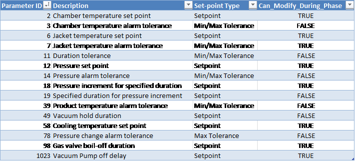
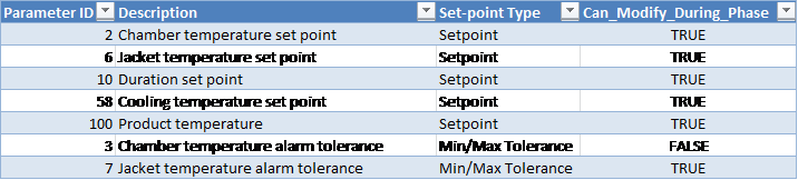
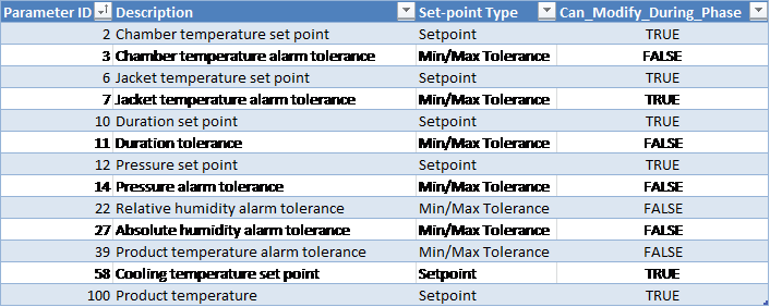
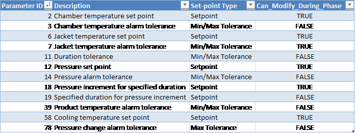
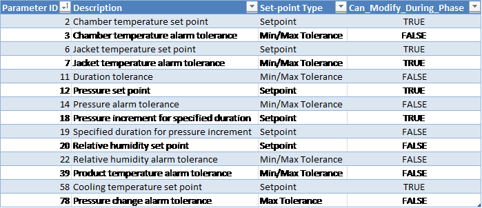
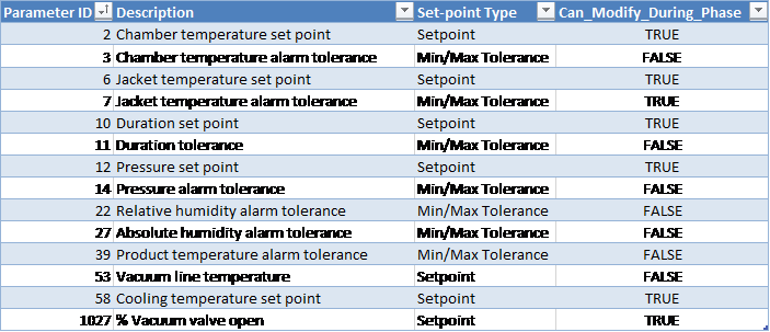
Operational Parameters
|
Parameter ID |
Description |
Set-point Type |
Can Modify During Phase |
|---|---|---|---|
|
2 |
Chamber temperature set point |
Setpoint |
TRUE |
|
3 |
Chamber temperature alarm tolerance |
Min/Max Tolerance |
FALSE |
|
6 |
Jacket temperature set point |
Setpoint |
TRUE |
|
7 |
Jacket temperature alarm tolerance |
Min/Max Tolerance |
TRUE |
|
10 |
Duration set point |
Setpoint |
TRUE |
|
11 |
Duration tolerance |
Min/Max Tolerance |
FALSE |
|
12 |
Pressure set point |
Setpoint |
TRUE |
|
14 |
Pressure alarm tolerance |
Min/Max Tolerance |
FALSE |
|
22 |
Relative humidity alarm tolerance |
Min/Max Tolerance |
FALSE |
|
27 |
Absolute humidity alarm tolerance |
Min/Max Tolerance |
FALSE |
|
39 |
Product temperature alarm tolerance |
Min/Max Tolerance |
FALSE |
|
58 |
Cooling temperature set point |
Setpoint |
TRUE |
|
1027 |
% Vacuum valve open |
Setpoint |
TRUE |
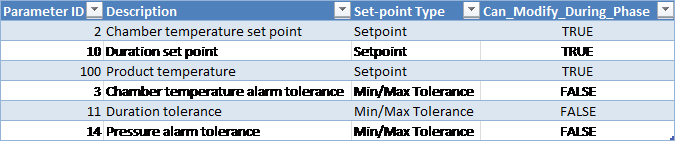
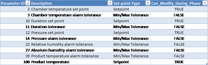
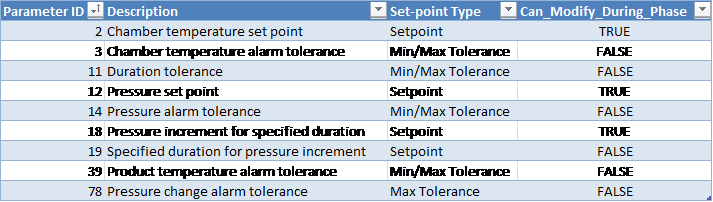
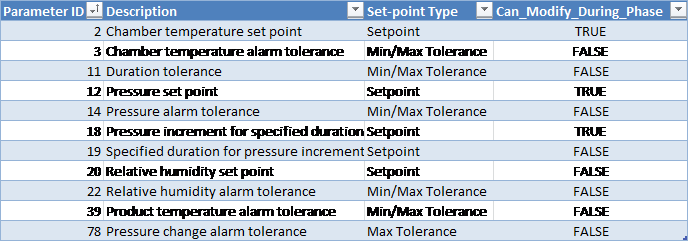
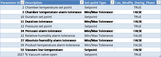
Customer Parameters
|
Parameter ID |
Description |
Set-point Type |
Can Modify During Phase |
|---|---|---|---|
|
2 |
Chamber temperature set point |
Setpoint |
TRUE |
|
3 |
Chamber temperature alarm tolerance |
Min/Max Tolerance |
FALSE |
|
10 |
Duration set point |
Setpoint |
TRUE |
|
11 |
Duration tolerance |
Min/Max Tolerance |
FALSE |
|
12 |
Pressure set point |
Setpoint |
TRUE |
|
14 |
Pressure alarm tolerance |
Min/Max Tolerance |
FALSE |
|
22 |
Relative humidity alarm tolerance |
Min/Max Tolerance |
FALSE |
|
27 |
Absolute humidity alarm tolerance |
Min/Max Tolerance |
FALSE |
|
39 |
Product temperature alarm tolerance |
Min/Max Tolerance |
FALSE |
|
1027 |
% Vacuum valve open |
Setpoint |
TRUE |
Periodically Reported Device Measurements
The following information will be periodically reported throughout the phase. The duration between each record insert is defined in section Chamber Configuration (Equipment/Phase Config) of the chamber configuration parameters.
-
Time
-
Pressure
-
Pressure Set-point
-
Lowest and Highest Chamber Temperature
-
Product temperature
-
Relative Humidity (%RH) Device 49:
-
If RH sensor(s) is/are installed, this will show the Measured RH from the controlling sensor, OR
-
If no RH sensor is installed, this will show the %RH calculated based on the measured AH reading
-
-
AH Concentration (Device 85):
-
Depending on the configured HUT# template this is either the value measured by the Controlling AH sensor or it is the Measured Average reading from installed AH sensors)
-
Device Measurements Summary
The following information will be reported in the phase summary:
-
Phase Duration:
-
In-Spec Time (deviation raised if less than Minimum Duration Tolerance Parameter 11 Min)
-
Total Phase Time (deviation raised if exceeds Maximum Duration Tolerance Parameter 11 Max)
-
-
Minimum Pressure
-
Maximum Pressure
-
Minimum Chamber Temperature
-
Maximum Chamber Temperature
-
Final Relative Humidity
-
Final Absolute Humidity
-
Maximum Relative Humidity
-
Maximum Absolute Humidity
-
Minimum Product Temperature
-
Maximum Product Temperature
If any of the above device measurements fall outside of specified alarm tolerances, a deviation will be indicated on the report.
Phase Completion
The phase will be completed when the following is true.
-
The product temperature is not specified OR the product temperature is greater than or equal to the specified minimum tolerance (parameter 39 Min) AND
-
The RH is not specified OR the RH is greater than or equal to the minimum tolerance (parameter 22 Min) plus RH offset (equipment/phase parameter 70) AND
-
The AH is not specified OR the AH is greater than or equal to the minimum tolerance (parameter 27 Min) plus AH offset (equipment/phase parameter 71) AND
-
In-spec. time is greater than or equal to the duration set-point (parameter 10) OR In-spec. time is greater than or equal to the minimum tolerance (parameter 11 Min) and total phase-time elapsed is greater than or equal to the maximum duration tolerance (parameter 11 Max) less 1 minute.
Dynamic Conditioning with Air
This phase will dynamically condition the chamber by running the air and vacuum subsystems.
Note: The interlock conditions described in section Phase Start Interlocks for this phase must be met before it is allowed to start.
Active Subsystems
The following subsystems will be active during the phase:
-
Vacuum
-
Chamber Heat
-
Humidity Monitoring
-
Air
-
If the blower option is selected, then subsystem Re-circulation Blowers will be active as well.
-
If the product temperature option was selected, then subsystem Product Temperature Monitoring will be active as well.
Process
-
At the beginning of the phase the air pressure set-point will be set to the value in the cycle definition.
-
Air will be added in response to variations between the chamber pressure and the Pressure Set-point [Parameter 12].
-
When the chamber pressure is less than the phase pressure set-point [Parameter 12] minus the “pressure control offset” [Parameter 84], the vacuum subsystem will turn off.
-
During the phase, all pressure variations will be attributed to air.
-
The “% Vacuum Open” [Parameter 1027] will function as follows:
-
If no value is specified or the parameter is missing or the value is set to 100%:
-
Vacuum flow valve will remain fully open during normal phase operation
-
-
If a parameter value other than 100% is specified:
-
Vacuum flow valve will be set to the specified parameter 1027 value during the phase
-
-
Partial pressures will be handled as follows:
-
At the beginning of the phase the current value of the EO partial pressure will be stored, and the partial pressure of air will be changed to be the same as the pressure in the chamber.
-
The Dynamic Conditioning Timer is reset at the beginning of the Dynamic Conditioning with Air phase and will accumulate time while the following conditions are met:
-
Chamber pressure is less than the Dynamic Conditioning Timer Max Pressure [CH_CD[0].DEC_Press]
-
Air subsystem valves are in a state which allows injection of Air
-
Vacuum system valves and pumps are in a state which allows chamber gasses to be extracted
-
-
If, at the end of the phase, the Dynamic Conditioning Timer value is less than the Dynamic Conditioning Timer Minimum Duration [CH_CD[0].DEC_Dur], the chamber pressure will be distributed as follows:
-
If the chamber pressure is greater than the stored EO partial pressure, the EO partial pressure will be re-set to the stored value and the remaining chamber pressure will be placed in the air partial pressure.
-
If the chamber pressure is less than or equal to the stored EO partial pressure, then the EO partial pressure will be set to the chamber pressure and the air partial pressure will be set to 0.
-
Chamber Configurable Parameters
|
Parameter ID |
Description |
Set-point Type |
Can Modify During Phase |
|---|---|---|---|
|
84 |
Pressure control offset |
Setpoint |
TRUE |
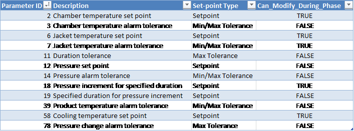
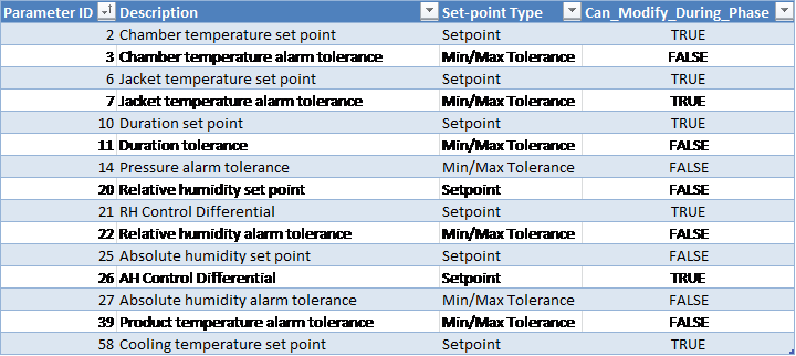
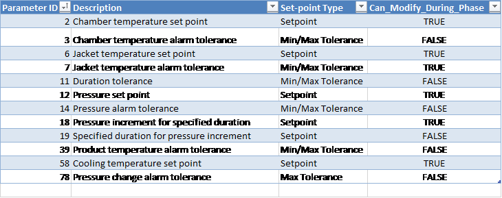
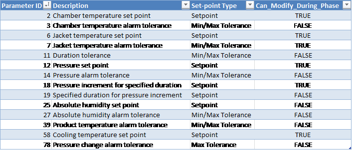
Operational Parameters
|
Parameter ID |
Description |
Set-point Type |
Can Modify During Phase |
|---|---|---|---|
|
2 |
Chamber temperature set point |
Setpoint |
TRUE |
|
3 |
Chamber temperature alarm tolerance |
Min/Max Tolerance |
FALSE |
|
6 |
Jacket temperature set point |
Setpoint |
TRUE |
|
7 |
Jacket temperature alarm tolerance |
Min/Max Tolerance |
TRUE |
|
10 |
Duration set point |
Setpoint |
TRUE |
|
11 |
Duration tolerance |
Min/Max Tolerance |
FALSE |
|
12 |
Pressure set point |
Setpoint |
TRUE |
|
14 |
Pressure alarm tolerance |
Min/Max Tolerance |
FALSE |
|
22 |
Relative humidity alarm tolerance |
Min/Max Tolerance |
FALSE |
|
27 |
Absolute humidity alarm tolerance |
Min/Max Tolerance |
FALSE |
|
39 |
Product temperature alarm tolerance |
Min/Max Tolerance |
FALSE |
|
58 |
Cooling temperature set point |
Setpoint |
TRUE |
|
1027 |
% Vacuum valve open |
Setpoint |
TRUE |
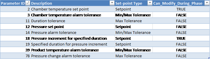
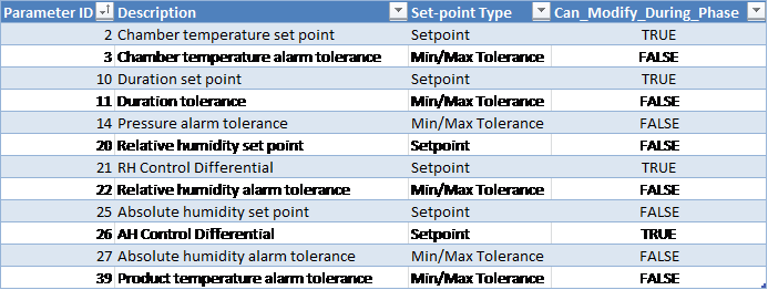
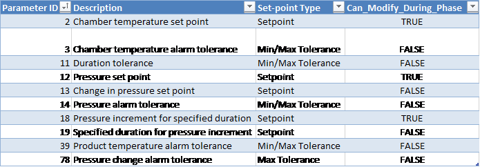
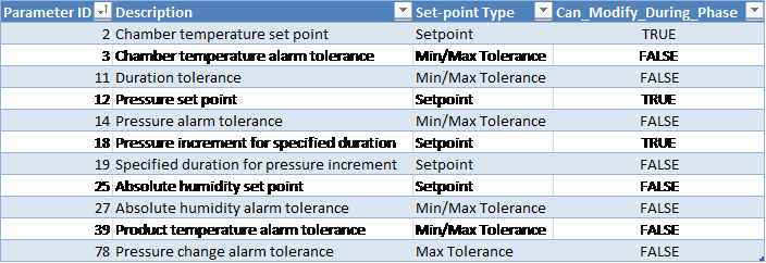
Customer Parameters
|
Parameter ID |
Description |
Set-point Type |
Can Modify During Phase |
|---|---|---|---|
|
2 |
Chamber temperature set point |
Setpoint |
TRUE |
|
3 |
Chamber temperature alarm tolerance |
Min/Max Tolerance |
FALSE |
|
10 |
Duration set point |
Setpoint |
TRUE |
|
11 |
Duration tolerance |
Min/Max Tolerance |
FALSE |
|
12 |
Pressure set point |
Setpoint |
TRUE |
|
14 |
Pressure alarm tolerance |
Min/Max Tolerance |
FALSE |
|
22 |
Relative humidity alarm tolerance |
Min/Max Tolerance |
FALSE |
|
27 |
Absolute humidity alarm tolerance |
Min/Max Tolerance |
FALSE |
|
39 |
Product temperature alarm tolerance |
Min/Max Tolerance |
FALSE |
|
1027 |
% Vacuum valve open |
Setpoint |
TRUE |
Periodically Reported Device Measurements
The following information will be periodically reported throughout the phase. The duration between each record insert is defined in section Run Record Inserts of the chamber configuration parameters.
-
Time
-
Pressure
-
Pressure Set-point
-
Lowest and Highest Chamber Temperature
-
Product temperature
-
Relative Humidity (%RH) Device 49:
-
If RH sensor(s) is/are installed, this will show the Measured RH from the controlling sensor, OR
-
If no RH sensor is installed, this will show the %RH calculated based on the measured AH reading
-
-
AH Concentration (Device 85):
-
Depending on the configured HUT# template this is either the value measured by the Controlling AH sensor or it is the Measured Average reading from installed AH sensors)
-
Device Measurements Summary
The following information will be reported in the phase summary:
-
Phase Duration
-
In-Spec Time (Device 141) – if less than Minimum Duration Tolerance [Parameter 11 Min], a deviation will be indicated on the report
-
Total Phase Time (Device 144) – if greater than Maximum Duration Tolerance [Parameter 11 Max], a deviation will be indicated on the report
-
-
Minimum Pressure
-
Maximum Pressure
-
Minimum Chamber Temperature
-
Maximum Chamber Temperature
-
Final Relative Humidity
-
Final Absolute Humidity
-
Maximum Relative Humidity
-
Maximum Absolute Humidity
-
Minimum Product Temperature
-
Maximum Product Temperature
If any of the above device measurements fall outside of specified alarm tolerances, a deviation will be indicated on the report.
Phase Completion
The phase will be completed when the following is true.
-
The product temperature is not specified OR the product temperature is greater than or equal to the specified minimum tolerance (parameter 39 Min) AND
-
The RH is not specified OR the RH is greater than or equal to the minimum tolerance (parameter 22 Min) plus RH offset (equipment/phase parameter 70) AND
-
The AH is not specified OR the AH is greater than or equal to the minimum tolerance (parameter 27 Min) plus AH offset (equipment/phase parameter 71) AND
-
In-spec. time is greater than or equal to the duration set-point (parameter 10) OR In-spec. time is greater than or equal to the minimum tolerance (parameter 11 Min) and total phase-time elapsed is greater than or equal to the maximum duration tolerance (parameter 11 Max) less 1 minute.
EO Inject via Pressure
EO gas is injected until a pressure set-point is met.
Note: The interlock conditions described in section Phase Start Interlocks for this phase must be met before it is allowed to start.
Active Subsystems
The following subsystems are active during this process phase:
-
Chamber Heat
-
EO Gas Monitoring
-
Drum Weight Monitoring
-
Ethylene Oxide
-
If the blower option is selected, then subsystem Re-circulation Blowers is active as well.
-
If the product temperature option was selected, then subsystem Product Temperature Monitoring is active as well.
Process
-
The system uses the “EO inject temperature alarm minimum/maximum tolerance” parameter to ensure that the EO temperature is within an acceptable range.
-
The system will raise an alarm and not allow inject to proceed if the temperature is not within the allowed range.
-
-
The phase may not start/proceed until the EO drum net weight is greater than the configurable “EO drum empty net weight” parameter value and the Tank ID has been entered into the system.
-
If the drum net weight falls below the configurable “EO drum empty net weight”, the drum is considered to be empty and the system will raise an alarm and place the chamber on Hold.
-
“Maximum measured gross weight for vacant EO scale” parameter is used to determine if a drum has been removed from the weigh scale. When the gross weight falls below this value, the scale is considered to be vacant (i.e. no drum is on the scale).
-
A minimum gross weight of an EO drum must be registered on the scale before the system accepts the tank (this minimum gross weight is defined by parameter 94).
-
-
Stagnant weight duration: amount of time (in seconds) that the system will wait before placing the chamber on Hold (and generating an alarm) if the EO drum weight does not change by more than the “EO stagnant weight amount” parameter value.
-
Equipment/phase General Configuration Parameter 1005: EO weigh scale wait duration (in seconds) that the system will wait after EO subsystem valves close before allowing drum change or Run mode.
-
Used to allow the EO weight to settle.
-
-
At the end of the phase the Tank ID and weight are reported on the process report.
-
As per the cycle definition value-validation rules (section Value Validation), either pressure set-point or pressure change set-point can be set for this phase. If the “change in pressure set-point” parameter is set, system will obtain the absolute pressure set-point as follows:
-
Absolute pressure set-point = value of the actual measured pressure at the start of the phase + “change in pressure set-point” parameter value.
-
-
If the pressure set-point is reached, the system will stop injection.
-
If the pressure exceeds the “pressure set point for abort” parameter value, the cycle will be automatically aborted (system initiates EO abort sequence).
-
If the EO concentration exceeds the “EO concentration maximum alarm tolerance”, an alarm will be raised and the cycle will be placed on Hold. Operator intervention will be required to put the chamber back into Run and continue the cycle.
-
If the used EO weight exceeds the “weight maximum tolerance”, an alarm will be raised and the cycle will be placed on Hold. Operator intervention will be required to put the chamber back into Run and continue the cycle.
-
Pressure increment for specified duration (parameter 18): defines how much the pressure should change during the specified duration interval (parameter 19, in seconds).
-
“Pressure change allowed during phase” (parameter 77) is a delta pressure parameter which is not mapped to the process controller
-
The system will calculate the difference between the measured minimum and maximum pressures during the phase
-
If this measurement falls outside of the minimum and maximum tolerance defined by parameter 77, a deviation will be indicated on the report
-
If no tolerance for parameter 77 is defined, the delta pressure will not be reported in the phase summary and no deviations will be raised
-
-
If the pressure changes by more than the “pressure change alarm tolerance” parameter during the specified duration for pressure increment, an alarm is raised and chamber goes on Hold.
-
Gas valve boil-off duration [Parameter 98]:
-
When the phase completes, the gas valve(s) will remain open for the specified time period
-
If chamber enters Hold or Stop mode during a boil-off, then the gas valve(s) will close and the Gas Valve Boil-Off Duration [Phase Parameter 98] will be paused. The boil-off will resume for the remainder of the Gas Valve Boil-Off Duration when the chamber is put back in Run.
-
If the boil-off period started in a previous phase, then the boil-off will use the duration from the previous phase's Parameter 98, unless the current phase is Vacuum and it has a boil-off duration set greater than zero (0).
-
If the boil-off duration period continues into a Nitrogen Inject phase, the remaining boil-off time will be cancelled.
-
Boil-off will only be allowed during Normal cycle sequence.
-
-
N2 purge duration: if available for your chamber will occur at end of phase
-
Gas valve boil off is open and nitrogen valve opens for this purge duration to purge EO from the pipe line.
-
-
Alarm 372: if the chamber pressure is greater than or equal to the customer-specified maximum pressure (parameter 1028), an alarm will be raised.
-
EO-CO2 Gas Mix Percentage [Parameter 30]:
-
If Parameter 30 is undefined (null), or has a value less than or equal to 1%: the value will be taken as 100% EO.
-
Any value greater than 1% will define the percentage of EO that is in the EO-CO2 mixture.
-
When Parameter 30 is used, its value will determine the percentage of the change in pressure in the current phase that is attributed to EO. The remaining pressure change in the current phase will be attributed to Nitrogen.
-
Sample calculation:
Part_press_N2 = Part_press_N2_O + Press_delta * (1 – EO_Percent)
Part_Press_EO = Part_Press_EO_O + Press_delta * EO_Percent
Where:
Part_press_N2 = Resultant partial pressure of Nitrogen (inert gas)
Part_press_N2_O = Initial partial pressure of Nitrogen (inert gas)
Press_delta = Pressure rise during the current phase
EO_Percent = Value of Parameter 30 set for the current phase
Part_Press_EO = Resultant partial pressure of EO gas
Part_Press_EO_O = Initial partial pressure of EO gas
Chamber Configurable Parameters

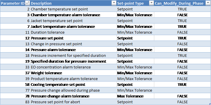
Operational Parameters
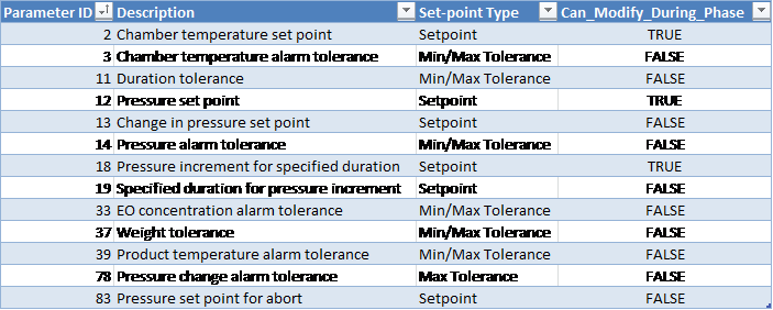
Customer Parameters
Periodically Reported Device Measurements
The following information is periodically reported throughout the phase. The duration between each record insert is defined in section Run Record Inserts of the chamber configuration parameters.
-
Time
-
Pressure
-
Pressure Set-point
-
Lowest and Highest Chamber Temperature
-
Product temperature
-
Measured EO Concentration (Device 53):
-
Depending on the configured EOT# template this is either the value measured by the Controlling EO sensor or it is the Measured Average reading from installed EO sensors
-
-
EO Drum Weight (used)
Device Measurements Summary
The following information will be reported in the phase summary:
-
Phase Duration:
-
In-Spec Time (deviation raised if less than Minimum Duration Tolerance Parameter 11 Min)
-
Total Phase Time (deviation raised if exceeds Maximum Duration Tolerance Parameter 11 Max)
-
-
Final Pressure
-
Minimum Chamber Temperature
-
Maximum Chamber Temperature
-
Final EO Concentration
-
EO Weight Used of each drum that was configured during the phase
-
Total EO Weight Used during the phase
-
Minimum Product Temperature
-
Maximum Product Temperature
If any of the above device measurements fall outside of specified alarm tolerances, a deviation will be indicated on the report.
If Alarm 372 was raised during the phase, a deviation will be indicated on the report.
Phase Completion
The phase is completed when one of the following is true.
-
Pressure is greater than or equal to the set-point (parameter 12) and elapsed phase time is greater than or equal to the minimum duration tolerance (parameter 11 Min)
-
Pressure is greater than or equal to the minimum tolerance (parameter 14 Min) plus the pressure offset (equipment/phase parameter 69 Min) and elapsed phase time is greater than or equal to the maximum duration tolerance (parameter 11 Max) less one minute
-
Pressure is greater than the maximum tolerance (parameter 14 Max)
EO Inject via Concentration
EO gas will be injected until measured EO concentration set-point or absolute pressure set-point is met.
Note: The interlock conditions described in section Phase Start Interlocks for this phase must be met before it is allowed to start.
Active Subsystems
The following subsystems are active during this process phase:
-
Chamber Heat
-
EO Gas Monitoring
-
Drum Weight Monitoring
-
Ethylene Oxide
-
If the blower option is selected, then subsystem Re-circulation Blowers is active as well.
-
If the product temperature option was selected, then subsystem Product Temperature Monitoring is active as well.
Process
-
The system will use the “EO inject temperature alarm minimum/maximum tolerance” parameter to ensure that the EO temperature is within an acceptable range.
-
The system will raise an alarm and not allow inject to proceed if the temperature is not within the allowed range.
-
-
The phase may not start/proceed until the EO drum net weight is greater than the configurable “EO drum empty net weight” parameter value and the Tank ID has been entered into the system.
-
If the drum net weight falls below the configurable “EO drum empty net weight”, the drum is considered to be empty and the system will raise an alarm and place the chamber on Hold.
-
“Maximum measured gross weight for vacant EO scale” parameter is used to determine if a drum has been removed from the weigh scale. When the gross weight falls below this value, the scale is considered to be vacant (i.e. no drum is on the scale).
-
A minimum gross weight of an EO drum must be registered on the scale before the system accepts the tank (this minimum gross weight is defined by parameter 94).
-
-
Stagnant weight delay: amount of time (in seconds) that the system will wait before placing the chamber on Hold (and generating an alarm) if the EO drum weight does not change by more than the “EO stagnant weight amount” parameter value.
-
Weigh scale wait duration: duration (in seconds) that the system will wait after EO subsystem valves close before allowing drum change. Used to allow the EO weight to settle.
-
At the end of the phase the Tank ID and weight are reported on the process report.
-
If the pressure or concentration set-point (parameters 12 and 31) is reached, the system will stop injection.
-
If the pressure exceeds the “pressure set point for abort” parameter value, the cycle will be automatically aborted (system initiates EO abort sequence).
-
If the EO concentration exceeds the “EO concentration maximum alarm tolerance”, an alarm will be raised and the cycle will be placed on Hold. Operator intervention will be required to put the chamber back into Run and continue the cycle.
-
If the used EO weight exceeds the “weight maximum tolerance”, an alarm will be raised and the cycle will be placed on Hold. Operator intervention will be required to put the chamber back into Run and continue the cycle.
-
Pressure increment for specified duration (parameter 18): defines how much the pressure should change during the specified duration interval (parameter 19, in seconds).
-
If the pressure changes by more than the “pressure change alarm tolerance” parameter during the specified duration for pressure increment, an alarm is raised and chamber goes on Hold.
-
Gas valve boil-off duration [Parameter 98]:
-
When the phase completes, the gas valve(s) will remain open for the specified time period
-
If chamber enters Hold or Stop mode during a boil-off, then the gas valve(s) will close and the Gas Valve Boil-Off Duration [Phase Parameter 98] will be paused. The boil-off will resume for the remainder of the Gas Valve Boil-Off Duration when the chamber is put back in Run.
-
If the boil-off period started in a previous phase, then the boil-off will use the duration from the previous phase's Parameter 98, unless the current phase is Vacuum and it has a boil-off duration set greater than zero (0).
-
If the boil-off duration period continues into a Nitrogen Inject phase, the remaining boil-off time will be cancelled
-
Boil-off will only be allowed during Normal cycle sequence.
-
-
N2 purge duration: if available for your chamber will occur at end of phase
-
Gas valve boil off is open and nitrogen valve opens for this purge duration to purge EO from the pipe line.
-
-
Alarm 372: if the chamber pressure is greater than or equal to the customer-specified maximum pressure (parameter 1028), an alarm will be raised.
-
EO-CO2 Gas Mix Percentage [Parameter 30]:
-
If Parameter 30 is undefined (null), or has a value less than or equal to 1%: the value will be taken as 100% EO.
-
Any value greater than 1% will define the percentage of EO that is in the EO-CO2 mixture.
-
When Parameter 30 is used, its value will determine the percentage of the change in pressure in the current phase that is attributed to EO. The remaining pressure change in the current phase will be attributed to Nitrogen.
-
Sample calculation:
Part_press_N2 = Part_press_N2_O + Press_delta * (1 – EO_Percent)
Part_Press_EO = Part_Press_EO_O + Press_delta * EO_Percent
Where:
Part_press_N2 = Resultant partial pressure of Nitrogen (inert gas)
Part_press_N2_O = Initial partial pressure of Nitrogen (inert gas)
Press_delta = Pressure rise during the current phase
EO_Percent = Value of Parameter 30 set for the current phase
Part_Press_EO = Resultant partial pressure of EO gas
Part_Press_EO_O = Initial partial pressure of EO gas
Chamber Configurable Parameters

Operational Parameters
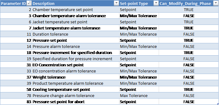
Customer Parameters
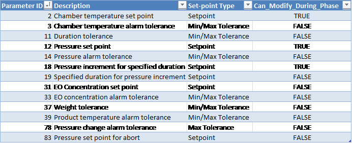
Periodically Reported Device Measurements
The following information is periodically reported throughout the phase. The duration between each record insert is defined in section Run Record Inserts of the chamber configuration parameters.
-
Time
-
Pressure
-
Pressure Set-point
-
Lowest and Highest Chamber Temperature
-
Product temperature
-
Measured EO Concentration (Device 53):
-
Depending on the configured EOT# template this is either the value measured by the Controlling EO sensor or it is the Measured Average reading from installed EO sensors
-
-
EO Drum Weight (used)
Device Measurements Summary
The following information will be reported in the phase summary:
-
Phase Duration:
-
In-Spec Time (deviation raised if less than Minimum Duration Tolerance Parameter 11 Min)
-
Total Phase Time (deviation raised if exceeds Maximum Duration Tolerance Parameter 11 Max)
-
-
Final Pressure
-
Minimum Chamber Temperature
-
Maximum Chamber Temperature
-
Final EO Concentration
-
EO Weight Used of each drum that was configured during the phase
-
Total EO Weight Used during the phase
-
Minimum Product Temperature
-
Maximum Product Temperature
Note:
If any of the above device measurements fall outside of specified alarm tolerances, a deviation will be indicated on the report.
If Alarm 372 was raised during the phase, a deviation will be indicated on the report.
Phase Completion
The phase is completed when one of the following is true.
-
Pressure is greater than or equal to the set-point (parameter 12) and elapsed phase time is greater than or equal to the minimum duration tolerance (parameter 11 Min).
-
Pressure is greater than or equal to the minimum tolerance (parameter 14 Min) plus the pressure offset (equipment/phase parameter 69 Min) and elapsed phase time is greater than or equal to the maximum duration tolerance (parameter 11 Max) less one minute
-
Measured EO concentration is greater than or equal to the set-point (parameter 31) and pressure is greater than or equal to the minimum tolerance (parameter 14 Min) plus the pressure offset (equipment/phase parameter 69 Min) and elapsed phase time is greater than or equal to the minimum duration tolerance (parameter 11 Min)
-
Measured EO concentration is greater than or equal to the minimum tolerance (parameter 33 Min) plus the EO concentration offset (equipment/phase parameter 72 Min) and elapsed phase time is greater than or equal to the maximum duration tolerance (parameter 11 Max) less one minute
-
Pressure is greater than the phase maximum tolerance (parameter 14 Max)
EO Inject via Weight
EO gas will be injected until EO weight set-point or absolute pressure set-point is met.
Note: The interlock conditions described in section Phase Start Interlocks for this phase must be met before it is allowed to start.
Active Subsystems
The following subsystems are active during this process phase:
-
Chamber Heat
-
EO Gas Monitoring
-
Drum Weight Monitoring
-
Ethylene Oxide
-
If the blower option is selected, then subsystem Re-circulation Blowers is active as well.
-
If the product temperature option was selected, then subsystem Product Temperature Monitoring is active as well.
Process
-
The system will use the “EO inject temperature alarm minimum/maximum tolerance” parameter to ensure that the EO temperature is within an acceptable range.
-
The system will raise an alarm and not allow inject to proceed if the temperature is not within the allowed range.
-
-
The phase may not start/proceed until the EO drum net weight is greater than the configurable “EO drum empty net weight” parameter value and the Tank ID has been entered into the system.
-
If the drum net weight falls below the configurable “EO drum empty net weight”, the drum is considered to be empty and the system will raise an alarm and place the chamber on Hold.
-
“Maximum measured gross weight for vacant EO scale” parameter is used to determine if a drum has been removed from the weigh scale. When the gross weight falls below this value, the scale is considered to be vacant (i.e. no drum is on the scale).
-
A minimum gross weight of an EO drum must be registered on the scale before the system accepts the tank (this minimum gross weight is defined by parameter 94).
-
-
Stagnant weight delay: amount of time (in seconds) that the system will wait before placing the chamber on Hold (and generating an alarm) if the EO drum weight does not change by more than the “EO stagnant weight amount” parameter value.
-
Weigh scale wait duration: duration (in seconds) that the system will wait after EO subsystem valves close before allowing drum change. Used to allow the EO weight to settle.
-
At the end of the phase the Tank ID and weight are reported on the process report.
-
If the pressure set-point is reached, the system will stop injection.
-
If the pressure exceeds the “pressure set point for abort” parameter value, the cycle will be automatically aborted (system initiates EO abort sequence).
-
If the EO concentration exceeds the “EO concentration maximum alarm tolerance”, an alarm will be raised and the cycle will be placed on Hold. Operator intervention will be required to put the chamber back into Run and continue the cycle.
-
If the used EO weight exceeds the “weight maximum tolerance”, an alarm will be raised and the cycle will be placed on Hold. Operator intervention will be required to put the chamber back into Run and continue the cycle.
-
Pressure increment for specified duration (parameter 18): defines how much the pressure should change during the specified duration interval (parameter 19, in seconds).
-
If the pressure changes by more than the “pressure change alarm tolerance” parameter during the specified duration for pressure increment, an alarm is raised and chamber goes on Hold.
-
Gas valve boil-off duration [Parameter 98]:
-
When the phase completes, the gas valve(s) will remain open for the specified time period
-
If chamber enters Hold or Stop mode during a boil-off, then the gas valve(s) will close and the Gas Valve Boil-Off Duration [Phase Parameter 98] will be paused. The boil-off will resume for the remainder of the Gas Valve Boil-Off Duration when the chamber is put back in Run.
-
If the boil-off period started in a previous phase, then the boil-off will use the duration from the previous phase's Parameter 98, unless the current phase is Vacuum and it has a boil-off duration set greater than zero (0).
-
If the boil-off duration period continues into a Nitrogen Inject phase, the remaining boil-off time will be cancelled
-
Boil-off will only be allowed during Normal cycle sequence.
-
-
N2 purge duration: if available for your chamber will occur at end of phase
-
Gas valve boil off is open and nitrogen valve opens for this purge duration to purge EO from the pipe line.
-
-
Alarm 372: if the chamber pressure is greater than or equal to the customer-specified maximum pressure (parameter 1028), an alarm will be raised.
EO-CO2 Gas Mix Percentage [Parameter 30]:
-
If Parameter 30 is undefined (null), or has a value less than or equal to 1%: the value will be taken as 100% EO.
-
Any value greater than 1% will define the percentage of EO that is in the EO-CO2 mixture.
-
When Parameter 30 is used, its value will determine the percentage of the change in pressure in the current phase that is attributed to EO. The remaining pressure change in the current phase will be attributed to Nitrogen.
Sample Calculation:
Part_press_N2 = Part_press_N2_O + Press_delta * (1 – EO_Percent)
Part_Press_EO = Part_Press_EO_O + Press_delta * EO_Percent
Where:
Part_press_N2 = Resultant partial pressure of Nitrogen (inert gas)
Part_press_N2_O = Initial partial pressure of Nitrogen (inert gas)
Press_delta = Pressure rise during the current phase
EO_Percent = Value of Parameter 30 set for the current phase
Part_Press_EO = Resultant partial pressure of EO gas
Part_Press_EO_O = Initial partial pressure of EO gas
Chamber Configurable Parameters

Operational Parameters
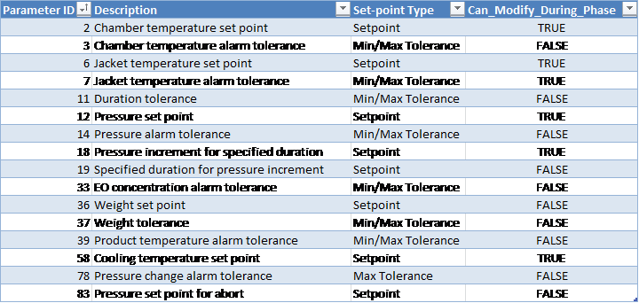
Customer Parameters
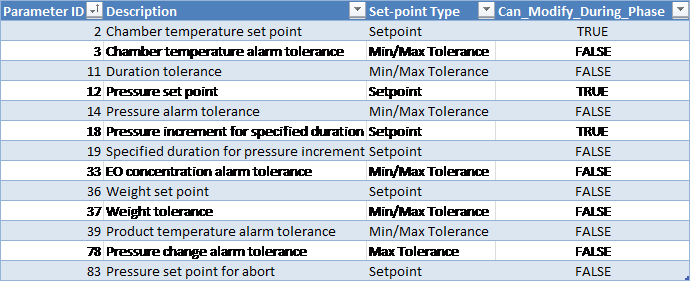
Periodically Reported Device Measurements
The following information is periodically reported throughout the phase. The duration between each record insert is defined in section Run Record Inserts of the chamber configuration parameters.
-
Time
-
Pressure
-
Pressure Set-point
-
Lowest and Highest Chamber Temperature
-
Product temperature
-
Measured EO Concentration (Device 53):
-
Depending on the configured EOT# template this is either the value measured by the Controlling EO sensor or it is the Measured Average reading from installed EO sensors
-
-
EO Drum Weight (used)
Device Measurements Summary
The following information will be reported in the phase summary:
-
Phase Duration
-
Final Pressure
-
Minimum Chamber Temperature
-
Maximum Chamber Temperature
-
Final EO Concentration
-
EO Weight Used of each drum that was configured during the phase
-
Total EO Weight Used during the phase
-
Minimum Product Temperature
-
Maximum Product Temperature
If any of the above device measurements fall outside of specified alarm tolerances, a deviation will be indicated on the report.
If Alarm 372 was raised during the phase, a deviation will be indicated on the report.
Phase Completion
The phase is completed when one of the following is true.
-
Pressure is greater than or equal to the set-point (parameter 12) and elapsed phase time is greater than or equal to the minimum duration tolerance (parameter 11 Min).
-
Pressure is greater than or equal to the minimum tolerance (parameter 14 Min) plus the pressure offset (equipment/phase parameter 69 Min) and elapsed phase time is greater than or equal to the maximum duration tolerance (parameter 11 Max) less one minute
-
EO weight used is greater than or equal to the phase EO weight set-point and pressure is greater than or equal to the minimum tolerance and elapsed phase time is greater than or equal to the minimum duration tolerance
-
EO weight used is greater than or equal to the minimum tolerance (parameter 37 Min) and elapsed phase time is greater than or equal to the maximum duration tolerance (parameter 11 Max) less one minute
-
Pressure is greater than the phase maximum tolerance (parameter 14 Max)
EO Dwell
EO dwell maintains EO gas within the chamber.
Note: The interlock conditions described in section Phase Start Interlocks for this phase must be met before it is allowed to start.
Active Subsystems
The following subsystems are active during this process phase:
-
Chamber Heat
-
EO Gas Monitoring
-
Drum Weight Monitoring (if EO make-up is enabled)
-
Ethylene Oxide (if EO make-up is enabled)
-
If the blower option is selected, then subsystem Re-circulation Blowers is active as well.
-
If the product temperature option was selected, then subsystem Product Temperature Monitoring is active as well.
-
Humidity Monitoring (if the “Report_AH_RH” parameter is enabled)
Process
-
Phase-start interlock: phase cannot start until average chamber temperature is greater than or equal to the minimum chamber temperature alarm tolerance (as defined in section 16.A).
-
The pressure set-point will be taken as follows:
-
If the specification parameter 12 is specified, then the system will use its value as the pressure set-point
-
If the specification parameter 12 is not specified (or zero), the system will use the final pressure of the previous phase as the pressure set-point
-
-
If the measured pressure goes above the pressure set-point plus the pressure control offset (parameter 84), the system will initiate vacuum to bring the pressure back down to the set-point (automatic vacuum).
-
If the “maximum number of make-ups” (parameter 54) is greater than zero, the system will add EO gas if either of the following conditions are true:
-
Absolute pressure drops below the pressure set-point minus “differential used for pressure control” (parameter 86), as long as the measured EO concentration is below the EO concentration set-point (parameter 31)
-
Measured EO concentration drops below the EO concentration set-point (parameter 31) minus the “Differential used in determining gas valve(s) opening” (parameter 32), as long as the measured chamber pressure is less than the pressure set-point
-
-
Once make-up is initiated, the system will inject EO into the chamber continuously until either of the following occurs:
-
Measured chamber pressure reaches the pressure set-point
-
Measured EO concentration reaches the EO concentration set-point (parameter 31)
-
-
Alarm 359: whenever EO make-up is initiated, the system will raise the event “Gas addition #n”, where #n is the total number of make-ups that have been initiated so far during the phase. The event will clear when the make-up segment is completed.
-
If the chamber goes on Hold (or Stop) mode before the initiated make-up is complete, the event will not be cleared. Chamber will continue make-up when it is put back into Run and Alarm 359 will be cleared only once the initiated make-up completes.
-
-
EO make-up will be enabled only if the “maximum number of make-ups” (parameter 54) is greater than zero.
-
As long as this parameter is greater than zero, an unlimited number of make-ups will be allowed
-
Alarm 203 will be raised if the number of make-ups exceeds the maximum number of make-ups from specification (parameter 54)
-
-
If EO make-up is enabled:
-
Alarm 22: if the used EO weight exceeds the maximum weight tolerance (parameter 37), an alarm will be raised
-
-
If the measured pressure exceeds the pressure set-point for abort (parameter 83), the cycle will be automatically aborted
-
Emission control output is turned on when:
-
The in-spec time is greater than or equal to the duration set-point minus the “emission control lead time” (parameter 55).
-
Elapsed phase time is greater than or equal to the maximum duration tolerance minus 1 minute.
-
-
Gas valve boil-off duration [Parameter 98]:
-
The gas valve(s) will remain open for the Gas Valve Boil-Off Duration. This will only occur one time, after a gas addition due to make-up has occurred.
-
If gas is still being injected, Boil-off will not occur.
-
If no gas addition has occurred, Boil-off will not occur.
-
When the phase completes, the gas valve(s) will remain open for the specified time period.
-
If no gas addition has occurred, Boil-off will not occur.
-
If chamber enters Hold or Stop mode during a boil-off, then the gas valve(s) will close and the Gas Valve Boil-Off Duration [Phase Parameter 98] will be paused. The boil-off will resume for the remainder of the Gas Valve Boil-Off Duration when the chamber is put back in Run..
-
If the boil-off period started in a previous phase, then the boil-off will use the duration from the previous phase's Parameter 98, unless the current phase is Vacuum and it has a boil-off duration set greater than zero (0).
-
If the boil-off duration period continues into a Nitrogen Inject phase, the remaining boil-off time will be cancelled
-
Boil-off will only be allowed during Normal cycle sequence.
-
-
N2 purge duration (parameter 99): occurs at end of phase, gas valve boil off is open and nitrogen valve opens for this purge duration to purge EO from the pipe line.
-
Alarm 372: if the chamber pressure is greater than or equal to the customer-specified maximum pressure (parameter 1028), an alarm will be raised.
-
EO-CO2 Gas Mix Percentage [Parameter 30]:
-
If Parameter 30 is undefined (null), or has a value less than or equal to 1%: the value will be taken as 100% EO.
-
Any value greater than 1% will define the percentage of EO that is in the EO-CO2 mixture.
-
When Parameter 30 is used, its value will determine the percentage of the change in pressure in the current phase that is attributed to EO. The remaining pressure change in the current phase will be attributed to Nitrogen.
Sample Calculation:
Part_press_N2 = Part_press_N2_O + Press_delta * (1 – EO_Percent)
Part_Press_EO = Part_Press_EO_O + Press_delta * EO_Percent
Where:
Part_press_N2 = Resultant partial pressure of Nitrogen (inert gas)
Part_press_N2_O = Initial partial pressure of Nitrogen (inert gas)
Press_delta = Pressure rise during the current phase
EO_Percent = Value of Parameter 30 set for the current phase
Part_Press_EO = Resultant partial pressure of EO gas
Part_Press_EO_O = Initial partial pressure of EO gas
-
Chamber Configurable Parameters
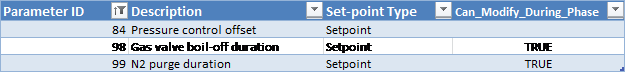
Operational Parameters
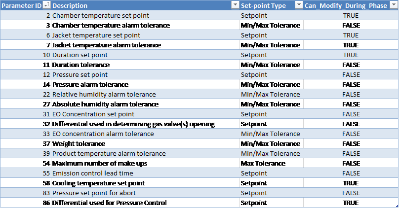
Customer Parameters
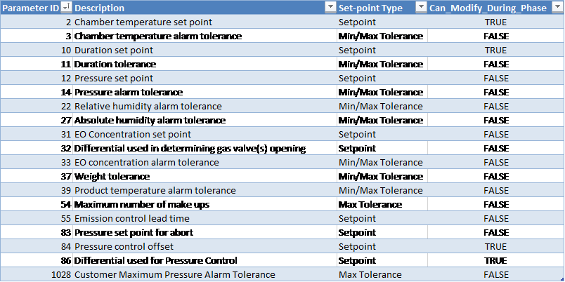
Periodically Reported Device Measurements
The following information is periodically reported throughout the phase. The duration between each record insert is defined in section Run Record Inserts of the chamber configuration parameters.
-
Time
-
Pressure
-
Pressure Set-point
-
Lowest and Highest Chamber Temperature
-
Product temperature
-
Measured EO Concentration (Device 53):
-
Depending on the configured EOT# template this is either the value measured by the Controlling EO sensor or it is the Measured Average reading from installed EO sensors
-
-
EO Drum Weight (used)
-
If product temperature phase option was NOT enabled for the cycle and Report_AH_RH system configuration parameter is true:
-
Relative Humidity (%RH) Device 49:
-
If RH sensor(s) is/are installed, this will show the Measured RH from the controlling sensor, OR
-
If no RH sensor is installed, this will show the %RH calculated based on the measured AH reading
-
-
AH Concentration (Device 85):
-
Depending on the configured HUT# template this is either the value measured by the Controlling AH sensor or it is the Measured Average reading from installed AH sensors)
-
-
Device Measurements Summary
The following information will be reported in the phase summary:
-
Phase Duration:
-
In-Spec Time (deviation raised if less than Minimum Duration Tolerance Parameter 11 Min)
-
Total Phase Time (deviation raised if exceeds Maximum Duration Tolerance Parameter 11 Max)
-
-
Minimum Pressure
-
Maximum Pressure
-
Minimum Chamber Temperature
-
Maximum Chamber Temperature
-
Minimum EO Concentration
-
Maximum EO Concentration
-
EO Weight Used of each drum that was configured during the phase
-
Total EO Weight Used during the phase
-
Minimum Product Temperature
-
Maximum Product Temperature
-
If product temperature phase option was NOT enabled for the cycle and Report_AH_RH system configuration parameter is true:
-
Minimum Relative Humidity
-
Maximum Relative Humidity
-
Minimum Absolute Humidity
-
Maximum Absolute Humidity
-
If any of the above device measurements fall outside of specified alarm tolerances, a deviation will be indicated on the report.
If Alarm 372 was raised during the phase, a deviation will be indicated on the report.
Phase Completion
The phase is completed when one of the following is true.
-
In-spec. time is greater than or equal to the duration set-point (parameter 10) AND product temperature is greater than or equal to the offset (Parameter 73) from the minimum product temperature alarm tolerance (Parameter 39 Minimum).
-
In-spec. time is greater than or equal to the duration minimum tolerance and total time elapsed is greater than or equal to the duration maximum tolerance less 1 minute AND product temperature is greater than or equal to the offset (Parameter 73) from the minimum product temperature alarm tolerance (Parameter 39 Minimum).
-
Pressure is greater than the phase maximum tolerance (parameter 14 Max)
-
Pressure is greater than abort pressure set-point (parameter 83) – cycle abort occurs
EO Dwell with Nitrogen Make-up
Maintains gas within the chamber and adds nitrogen as needed.
The interlock conditions described in section Phase Start Interlocks for this phase must be met before it is allowed to start.
Active Subsystems
The following subsystems are active during this process phase:
-
Chamber Heat
-
Nitrogen
-
If the blower option is selected, then subsystem Re-circulation Blowers is active as well.
-
If the product temperature option was selected, then subsystem Product Temperature Monitoring is active as well.
-
Humidity Monitoring
Process
-
The phase will not start until the chamber temperature is greater than or equal to the minimum chamber temperature alarm tolerance.
-
The pressure set-point will be taken as follows:
-
If the specification parameter 12 is specified, then the system will use its value as the pressure set-point
-
If the specification parameter 12 is not specified (or zero), the system will use the final pressure of the previous phase as the pressure set-point
-
-
If the measured pressure goes above the pressure set-point plus the pressure control offset (parameter 84), the system will initiate vacuum to bring the pressure back down to the set-point (automatic vacuum).
-
If the “maximum number of make-ups” (parameter 54) is greater than zero, the system will add nitrogen gas if the following occurs:
-
Absolute pressure drops below the pressure set-point minus “differential used for pressure control” (parameter 86)
-
-
Once make-up is initiated, the system will inject nitrogen into the chamber continuously until the following occurs:
-
Measured chamber pressure reaches the pressure set-point
-
-
Alarm 359: whenever nitrogen make-up is initiated, the system will raise the event “Gas addition #n”, where #n is the total number of make-ups that have been initiated so far during the phase. The event will clear when the make-up segment is completed.
-
If the chamber goes on Hold (or Stop) mode before the initiated make-up is complete, the event will not be cleared. Chamber will continue make-up when it is put back into Run and Alarm 359 will be cleared only once the initiated make-up completes.
-
-
Nitrogen make-up will be enabled only if the “maximum number of make-ups” (parameter 54) is greater than zero.
-
As long as this parameter is greater than zero, an unlimited number of make-ups will be allowed
-
Alarm 203 will be raised if the number of make-ups exceeds the maximum number of make-ups from specification (parameter 54)
-
-
If the pressure exceeds the “pressure set-point for abort” parameter value, the cycle will be automatically aborted
-
Emission control output is turned on when:
-
The in-spec time is greater than or equal to the duration set-point minus the “emission control lead time” (parameter 55).
-
-
Elapsed phase time is greater than or equal to the maximum duration tolerance minus 1 minute minus the “emission control lead time” (parameter 55).
-
Alarm 372: if the chamber pressure is greater than or equal to the customer-specified maximum pressure (parameter 1028), an alarm will be raised.
Operational Parameters
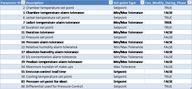
Customer Parameters
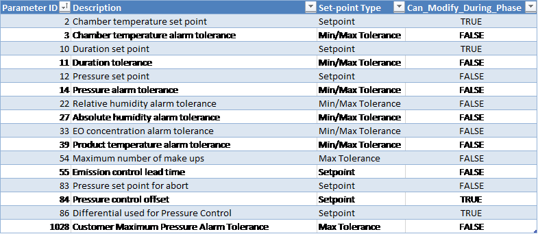
Periodically Reported Device Measurements
The following information is periodically reported throughout the phase. The duration between each record insert is defined in section Run Record Inserts of the chamber configuration parameters.
-
Time
-
Pressure
-
Pressure Set-point
-
Lowest and Highest Chamber Temperature
-
Product temperature
-
Measured EO Concentration (Device 53):
-
Depending on the configured EOT# template this is either the value measured by the Controlling EO sensor or it is the Measured Average reading from installed EO sensors
-
-
If product temperature phase option was NOT enabled for the cycle and Report_AH_RH system configuration parameter is true:
-
Relative Humidity (%RH) Device 49:
-
If RH sensor(s) is/are installed, this will show the Measured RH from the controlling sensor, OR
-
If no RH sensor is installed, this will show the %RH calculated based on the measured AH reading
-
-
AH Concentration (Device 85):
-
Depending on the configured HUT# template this is either the value measured by the Controlling AH sensor or it is the Measured Average reading from installed AH sensors)
-
-
Device Measurements Summary
The following information will be reported in the phase summary:
-
Phase Duration:
-
In-Spec Time (deviation raised if less than Minimum Duration Tolerance Parameter 11 Min)
-
Total Phase Time (deviation raised if exceeds Maximum Duration Tolerance Parameter 11 Max)
-
-
Minimum Pressure
-
Maximum Pressure
-
Minimum Chamber Temperature
-
Maximum Chamber Temperature
-
Minimum EO Concentration
-
Maximum EO Concentration
-
Minimum Product Temperature
-
Maximum Product Temperature
-
If product temperature phase option was NOT enabled for the cycle and Report_AH_RH system configuration parameter is true:
-
Minimum Relative Humidity
-
Maximum Relative Humidity
-
Minimum Absolute Humidity
-
Maximum Absolute Humidity
-
If any of the above device measurements fall outside of specified alarm tolerances, a deviation will be indicated on the report.
If Alarm 372 was raised during the phase, a deviation will be indicated on the report.
Phase Completion
The phase is completed when one of the following is true.
-
In-spec. time is greater than or equal to the duration set-point AND product temperature is greater than or equal to the offset (Parameter 73) from the minimum product temperature alarm tolerance (Parameter 39 Minimum).
-
In-spec. time is greater than or equal to the duration minimum tolerance (parameter 11 Min) and total time elapsed is greater than or equal to the duration maximum tolerance (parameter 11 Max) less 1 minute AND product temperature is greater than or equal to the offset (Parameter 73) from the minimum product temperature alarm tolerance (Parameter 39 Minimum).
-
Pressure is greater than the phase maximum tolerance (parameter 14 Max)
Air In-bleed
Allow air to enter the chamber until absolute pressure set-point is met following a pressure ramp.
Note: The interlock conditions described in section Interlocks for this phase must be met before it is allowed to start.
Active Subsystems
The following subsystems are active during this process phase:
-
Chamber Heat
-
Air
-
If the blower option is selected, then subsystem Re-circulation Blowers is active as well.
-
If the product temperature option was selected, then subsystem Product Temperature Monitoring is active as well.
Chamber Configurable Parameters

Process
-
The final air in-bleed phase cannot start if there is more than 13.5 mg/l of EO present in the chamber
-
Phase cannot start if more than 27 mg/l EO is present in the chamber
-
Door cannot be opened unless air in-bleed phase has been completed
-
Abort is not allowed during any Air In-bleed that occurs past the Abort 1 (i.e. non-EO) abort phase
-
Pressure increment for specified duration (parameter 18): defines how much the pressure should change during the specified duration interval (parameter 19, in seconds).
-
If the pressure changes by more than the “pressure change alarm tolerance” parameter during the specified duration for pressure increment, an alarm is raised and chamber goes on Hold
Operational Parameters
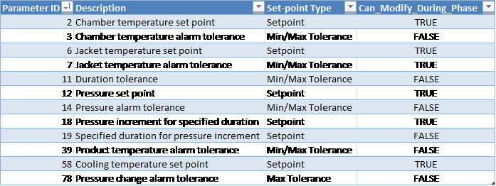
Customer Parameters
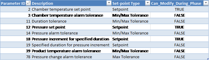
Periodically Reported Device Measurements
The following information is periodically reported throughout the phase. The duration between each record insert is defined in section Run Record Inserts of the chamber configuration parameters.
-
Time
-
Pressure
-
Pressure Set-point
-
Lowest and Highest Chamber Temperature
-
Product temperature
Device Measurements Summary
The following information will be reported in the phase summary:
-
Phase Duration:
-
In-Spec Time (deviation raised if less than Minimum Duration Tolerance Parameter 11 Min).
-
Total Phase Time (deviation raised if exceeds Maximum Duration Tolerance Parameter 11 Max).
-
Final Pressure
-
Minimum Chamber Temperature
-
Maximum Chamber Temperature
-
Minimum Product Temperature
-
Maximum Product Temperature
If any of the above device measurements fall outside of specified alarm tolerances, a deviation will be indicated on the report.
Phase Completion
The phase is completed when one of the following is true.
-
Pressure greater than or equal to the pressure set-point (parameter 12) and elapsed phase-time is greater than or equal to the minimum duration tolerance (parameter 11 Min)
-
Pressure is greater than or equal to the minimum tolerance (parameter 14 Min) plus the pressure offset (equipment/phase parameter 69 Min) and elapsed phase-time is greater than or equal to the maximum duration tolerance (parameter 11 Max) time less one minute
-
Pressure is greater than or equal to the maximum pressure alarm tolerance (parameter 14 Max)
Loop
The loop phase repeats sub-phases for the programmed repetition count. A loop phase may NOT include the following sub-phases:
-
Start-Up
-
Air Wash Loop
-
Nitrogen Wash Loop
-
Steam Conditioning Loop
Operational Parameters

Customer Parameters

Device Measurements Summary
The following information will be reported in the phase summary:
-
Total duration of the loop
-
Actual values of any loop parameters such as the loop count
-
Measured minimum and maximum values of any reported device within each loop sub-phase
The summary for loop phases will become available only when the cycle completes, i.e. when chamber enters Dormant sequence at the end of a run.
Phase Completion
The phase is completed when the current number of repetitions equals the loop count.
Air Wash Loop
The loop phase repeats sub-phases for the programmed repetition count. The air wash loop must have a minimum loop count and can only include the following sub-phases:
-
Air In-Bleed
-
Vacuum
-
Static Dwell
Operational Parameters
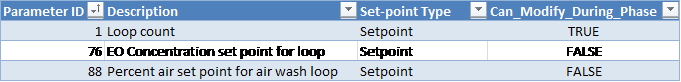
Customer Parameters

Device Measurements Summary
The following information will be reported in the phase summary:
-
Total duration of the loop
-
Actual values of any loop parameters such as the loop count
-
Measured minimum and maximum values of any reported device within each loop sub-phase
The summary for loop phases will become available only when the cycle completes, i.e. when chamber enters Dormant sequence at the end of a run.
Phase Completion
The phase is completed when the following conditions are satisfied:
-
Minimum loop count has been met AND
-
Loop count equals the optionally specified loop count set-point OR
-
Estimated % air is greater than or equal to the optionally specified % air set-point OR
-
Calculated EO concentration is less than the optionally specified EO Concentration Set-point AND, if available, measured EO concentration is less than the EO Concentration Set-point.
-
Nitrogen Wash Loop
The loop phase repeats sub-phases for the programmed repetition count. The nitrogen wash loop must have a minimum loop count and can only include the following sub-phases:
-
Nitrogen Inject
-
Steam Inject
-
Vacuum
-
Static Dwell
Operational Parameters

Customer Parameters

Device Measurements Summary
The following information will be reported in the phase summary:
-
Total duration of the loop
-
Actual values of any loop parameters such as the loop count
-
Measured minimum and maximum values of any reported device within each loop sub-phase.
The summary for loop phases will become available only when the cycle completes, i.e. when chamber enters Dormant sequence at the end of a run.
Phase Completion
The phase is completed when the following conditions are satisfied:
-
Minimum loop count has been met AND
-
Loop count equals the optionally specified loop count set-point OR
-
Calculated EO concentration is less than the optionally specified EO Concentration Set-point AND, if available, measured EO concentration is less than the optionally specified EO Concentration Set-point.
-
Steam Conditioning Loop
The loop phase repeats sub-phases for the programmed repetition count. The steam conditioning loop must have a minimum loop count and can only include the following sub-phases:
-
Nitrogen Inject
-
Steam Inject
-
Vacuum
-
Static Dwell
-
Conditioning Dwell via Pressure or RH
-
Continuous Steam Conditioning
Process
Alarm 455: when the loop duration exceeds the Maximum Duration Tolerance for Loop [Parameter 180], an alarm will be raised.
Operational Parameters
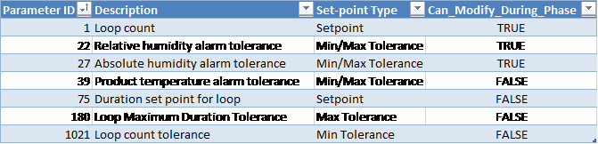
Customer Parameters

Device Measurements Summary
The following information will be reported in the phase summary:
-
Total duration of the loop
-
Actual values of any loop parameters such as the loop count
-
Measured minimum and maximum values of any reported device within each loop sub-phase
The summary for loop phases will become available only when the cycle completes, i.e. when chamber enters Dormant sequence at the end of a run.
Phase Completion
The phase is completed when the following conditions are satisfied:
-
Minimum loop count has been met AND
-
Loop duration is greater than or equal to the optionally specified Loop Duration Set-point OR
-
Loop count is equal to the optionally specified loop count set-point OR
-
Measured AH is within the optionally specified tolerance OR
-
Measured RH is within the optionally specified tolerance OR
-
Product Temperature is within the optionally specified tolerance
-
End Phase
The chamber enters the end phase after the final Air In-bleed indicating that the process has completed.
Active Subsystems
The following subsystems are active during this process phase:
-
Chamber Heat
-
Air
-
If the blower option is selected, then subsystem Re-circulation Blowers is active as well.
-
If the product temperature option was selected, then subsystem Product Temperature Monitoring is active as well.
Process
-
If the chamber sits in the End phase for longer than the “wash time delay” Parameter 143, the system will initiate an additional air wash (Vacuum followed by Air In-bleed).
-
The door cannot be opened until the pressure is greater than or equal to the “release door seal pressure” parameter value.
-
When chamber enters the End Phase, the system will start a timer:
-
When the timer reaches the “wash time delay” duration set-point (in seconds) and if the wash time delay is greater than zero, the system will initiate Vacuum and open the air in-bleed valve based on the “keep air in-bleed open during wash in end phase” option parameter
-
The system will stop Vacuum when the pressure set-point is reached. The air in-bleed will then allow the pressure to rise back up to “release door seal pressure” set-point.
-
The system will start the timer again and continue to loop Vacuum-air washes until the End Phase is completed.
-
-
If configured for your site, Unload button will become available once the chamber enters the End Phase. Clicking this button will complete the End Phase and put the chamber into dormant sequence.
-
The air/release valve BV-40 will remain open during the phase as long the pressure is less than the set-point
Note: Set the maximum pressure tolerance to an appropriately high value so that the system does not potentially raise a deviation. The End Phase maximum pressure tolerance should generally be the same value as was defined in the final Air In-bleed phase. The system does NOT use the maximum pressure tolerance for control during the End Phase.
Cycle Execution Options

Chamber Configurable Parameters

Operational Parameters
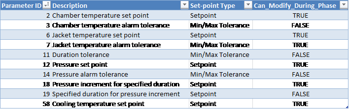
Customer Parameters
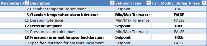
Periodically Reported Device Measurements
The following information is periodically reported throughout the phase. The duration between each record insert is defined in section Run Record Inserts of the chamber configuration parameters.
-
Time
-
Pressure
-
Pressure Set-point
-
Lowest and Highest Chamber Temperature
Device Measurements Summary
The following information will be reported in the phase summary:
-
Phase Duration:
-
In-Spec Time (deviation raised if less than Minimum Duration Tolerance Parameter 11 Min).
-
Total Phase Time (deviation raised if exceeds Maximum Duration Tolerance Parameter 11 Max).
-
-
Minimum Pressure
-
Maximum Pressure
-
Minimum Chamber Temperature
-
Maximum Chamber Temperature
-
Minimum Product Temperature
-
Maximum Product Temperature
-
Total number of phases executed (system will check to make sure all phases were executed and will raise a deviation if there are missing steps).
If any of the above device measurements fall outside of specified alarm tolerances, a deviation will be indicated on the report.
Phase Completion
The phase is completed when the chamber door is opened or Unload button is clicked.
Super-Atmospheric EO Dwell
The Super-Atmospheric EO Dwell phase will be used when chamber pressure is above atmosphere.
Active Subsystems
The following subsystems will be active during this process phase:
-
Chamber Heat
-
EO Gas Monitoring
-
Re-circulation Blowers (if enabled for the cycle).
-
Product Temperature Monitoring (if enabled for the cycle).
-
Humidity Monitoring (if the “Report_AH_RH” System Parameter is enabled).
Process
-
The pressure set-point will be taken as follows:
-
If the specification set-point [Parameter 12] is specified, then the system will use its value as the pressure set-point.
-
If the specification set-point [Parameter 12] is set to zero (or undefined), the system will use the final pressure of the previous phase as the pressure set-point.
-
-
Leak check will be performed as follows:
-
When the phase starts, the system will first wait for the Pressure Stabilization Delay [Parameter 257] to elapse, then
-
System will monitor the chamber pressure for the amount of time in Leak Check Duration [Parameter 258]:
-
During this time, if the pressure in the chamber drops faster than the Leak Check Pressure Rate [Parameter 259] per minute, Alarm 71 will be raised and configured by default to abort the cycle.
-
-
-
If the measured chamber pressure drops below the pressure set-point for abort [Parameter 83], alarm 548 will be raised and the cycle will be automatically aborted.
-
Emission control request DO-130 will turn on when:
-
In-spec time is greater than or equal to the duration set-point minus the “emission control lead time” [Parameter 55].
-
Total phase time is greater than or equal to the maximum duration tolerance minus 1 minute.
-
-
Alarm 372: if the chamber pressure is less than or equal to the customer-specified minimum pressure [Parameter 1028], an alarm will be raised.
-
[Parameter 1028] will be declared as a Min parameter.
-
Operational Parameters
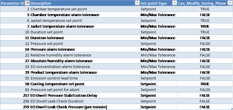
Checksum Parameters
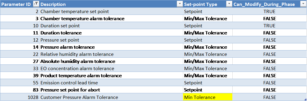
Equipment Phase Parameters
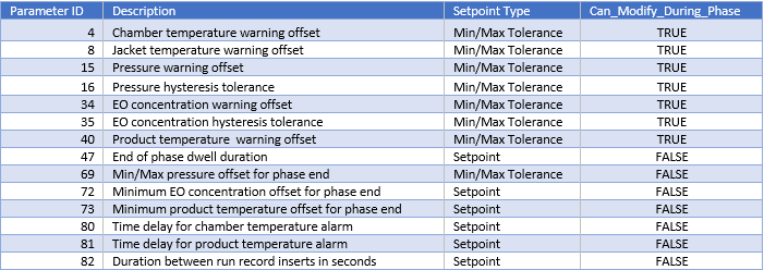
Cycle Execution Options
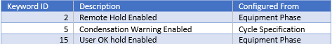
Periodically Reported Device Measurements
The following information will be periodically reported throughout the phase. The duration between each record insert will be defined by Equipment/Phase [Parameter 82].
-
Time
-
Pressure
-
Pressure Set-point
-
Lowest and Highest Chamber Temperature
-
Product temperature (if enabled)
-
Measured EO Concentration (Device 53):
-
Depending on the configured EOT# template this is either the value measured by the Controlling EO sensor or it is the Measured Average reading from installed EO sensors
-
-
If product temperature phase option was NOT enabled for the cycle and Report_AH_RH system configuration parameter is true:
-
Relative Humidity (%RH) Device 49:
-
If RH sensor(s) is/are installed, this will show the Measured RH from the controlling sensor, OR
-
If no RH sensor is installed and AI-169 is installed, this will show the %RH calculated based on the measured AH reading
-
If no RH device and AI-169 is not installed device 49 will show N/A on reports even if an AH sensor is installed and operating.
-
-
AH Concentration (Device 85):
-
Depending on the configured HUT# template this is either the value measured by the Controlling AH sensor or it is the Measured Average reading from installed AH sensors)
-
-
Device Measurements Summary
The following information will be reported in the phase summary:
-
Phase Duration:
-
In-Spec Time and
-
Total Phase Time
-
-
Minimum Pressure
-
Maximum Pressure
-
Minimum Chamber Temperature
-
Maximum Chamber Temperature
-
Minimum EO Concentration
-
Maximum EO Concentration
-
Minimum Product Temperature (if enabled)
-
Maximum Product Temperature (if enabled)
-
If product temperature phase option was NOT enabled for the cycle and Report_AH_RH system configuration parameter is true:
-
Minimum Relative Humidity
-
Maximum Relative Humidity
-
Minimum Absolute Humidity
-
Maximum Absolute Humidity
-
If any of the above device measurements fall outside of specified alarm tolerances, a deviation will be indicated on the report. For phase duration, a deviation will be raised if In-Spec Time is less than Minimum Duration Tolerance [Parameter 11 Min] or if Total Phase Time exceeds Maximum Duration Tolerance [Parameter 11 Max].
If Alarm 372 (chamber pressure less than or equal to [Parameter 1028]) was raised during the phase, a deviation will be indicated on the report.
Phase Completion
The phase will be completed when one of the following is true:
-
In-spec. time is greater than or equal to the duration set-point [Parameter 10] AND (if enabled) product temperature is greater than or equal to the equipment/phase offset [Parameter 73] from the minimum product temperature alarm tolerance [Parameter 39 Min].
-
In-spec. time is greater than or equal to the duration minimum tolerance [Parameter 11 Min] and total phase time elapsed is greater than or equal to the duration maximum tolerance [Parameter 11 Max] less 1 minute AND (if enabled) product temperature is greater than or equal to the offset [Parameter 73] from the minimum product temperature alarm tolerance (Parameter 39 Minimum).
-
Pressure is less than the phase minimum tolerance [Parameter 14 Min].
-
Pressure is less than abort pressure set-point [Parameter 83] – cycle abort occurs.