User Interfaces
The AccuSOLO system screens facilitate various functions described throughout this document. User interfaces support multiple languages and multiple units of measure. Any current screen can be printed to clipboard and to the default printer.
Customer Module
To access the Customer Module, click on the Customers button.
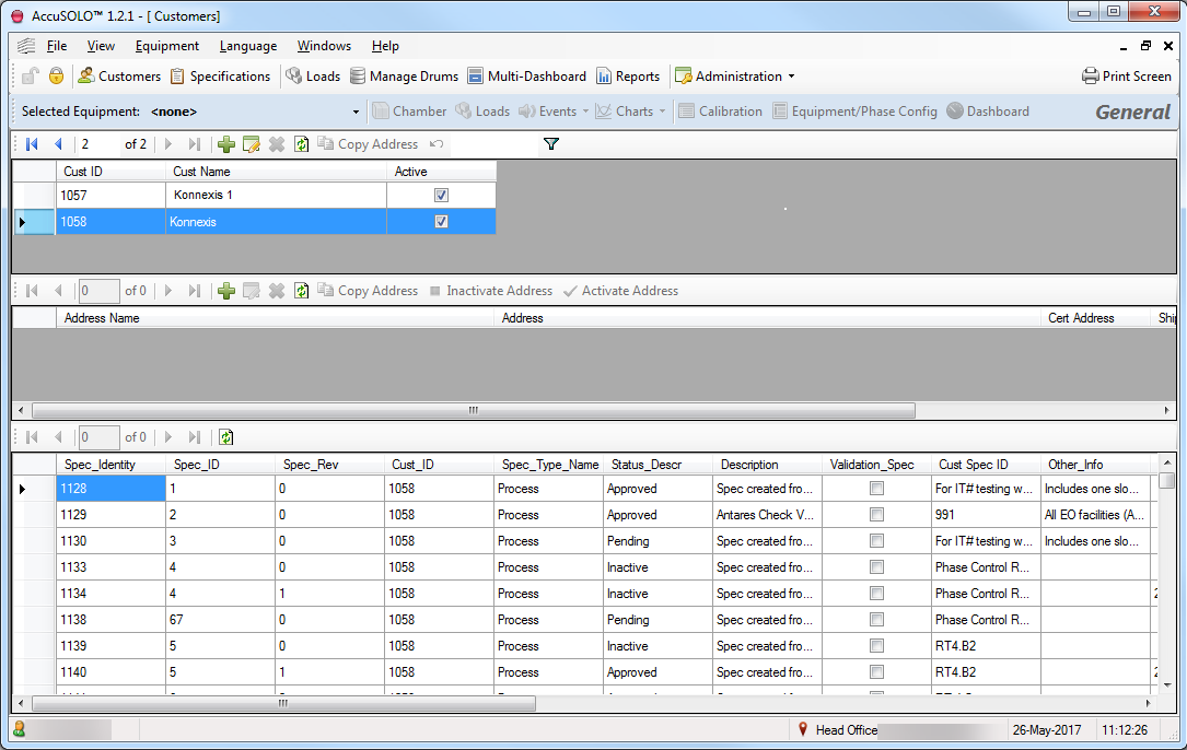
This module facilitates customer management including adding and deleting customers and creating specifications (cycle definitions) for existing customers. It has the capability of storing shipping addresses by customer as well as customer certificates. The following information is managed by this module:
-
Customer Information:
-
Customer ID
-
Customer Name
-
Customer Address
-
Customer Reference Type 1
-
Customer Reference Type 2
-
Active/Inactive
-
-
Shipping Address Information:
-
Address Name
-
Address
-
Certificate Address
-
Shipping Address
-
Invoice Address
-
Active/Inactive
-
-
Specifications (cycle definitions) – for more information on cycle definitions, refer to section Supported Phases.
Adding a Customer
-
To add a new customer, click the + button located in the customer section at the top of the pane
-
Under Cust Name type in the customer
-
Check the box under Active
-
When changing fields, software asks if you want to save changes, select YES
-
Add Address
-
Click the + in the address section
-
Type in Address Name and Address
-
Check the box next to the correct address type(s).
-
If address for the Cert, Ship and Invoice are different create a new address for each.
-
Check Active next to the address(es)
-
Removing a Customer
-
Highlight the Customer and Click the Delete icon
-
When asked “Are you sure you wish to delete the selected customer” click Yes
Note: The system will not allow deletion of customers to which specifications have been associated. Such customers can only be inactivated as described in the next section.
Copying, Inactivating, and Activating Address
-
Highlight address to be copied and click Copy Address
-
Highlight address and click Inactivate
-
Highlight address and click Activate
Specifications Module
To access the Specification Module, click the Specifications button.
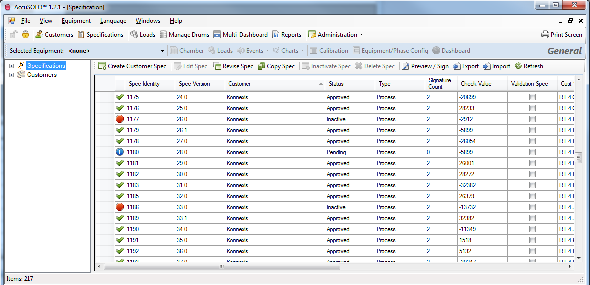
This module facilitates management of all specifications (cycle definitions). The following functions are available:
-
Create new customer specification
-
Different types of specification will be available depending on the configured equipment on a site:
-
Customer Spec for sites with Control System Equipment
-
Monitoring Spec for sites with Monitoring Equipment
-
-
Each newly created specification will obtain a unique specification identity, a unique Spec ID (for that customer) and a revision number of zero
-
Newly created (or revised) specifications will be in the Pending state
-
Specifications will enter the “Approved” state once the required number of e-signatures has been applied
-
Loads can only be built against approved specification
-
-
Edit customer specification
-
Only specifications in the Pending state are editable
-
Changing the customer for a pending specification will assign the next available Spec ID for the selected customer
-
-
Revise customer specification
-
Specifications in the Pending state cannot be revised
-
Revising an Approved customer specification will increment the revision number and set the state of the revised specification to Pending
-
Once the revised specification is approved, the previous revision will become inactive
-
It will be possible to revise an Inactive specification only if no other Pending or Approved versions of that specification exist
-
-
Copy customer specification
-
Copying a customer specification will create a replica of that specification with a new unique specification identity (and a unique Spec ID for that customer). Revision will be zero.
-
The system will assign the next available Spec ID for that customer
-
The replica specification will be in the Pending state
-
-
Delete customer specification
-
Only specifications which have not been used (i.e. have not been associated to a load) can be deleted
-
Approved or Inactive specifications cannot be deleted
-
-
Inactivate customer specification
-
Once a specification becomes inactive, it cannot be edited or used to build a load
-
-
Preview/Sign customer specification
-
Clicking the Preview/Sign button will present a Process Specification Report from where it will be possible to apply electronic signatures
-
Administration Module
This module facilitates management of administrative functions related to user management, group management, primary standard management and system configuration.
User Management Form
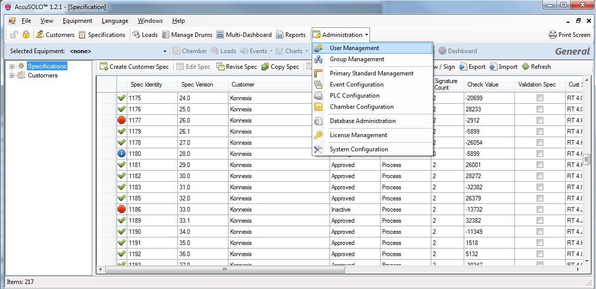
The user management form can be accessed via the Administration drop-down menu see User Interfaces.
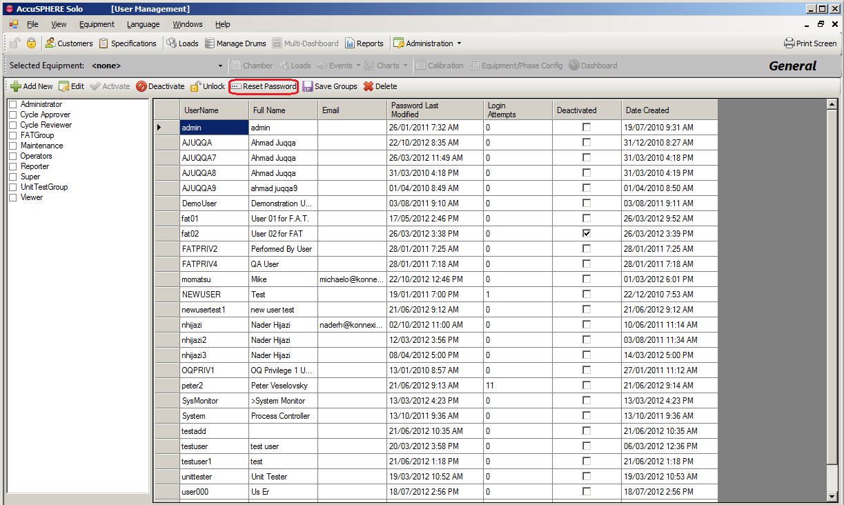
The User Management grid lists existing users and the groups to which they are associated. Each group can have multiple roles (i.e. system functions) assigned. For more information on Groups, see Group Management Form.
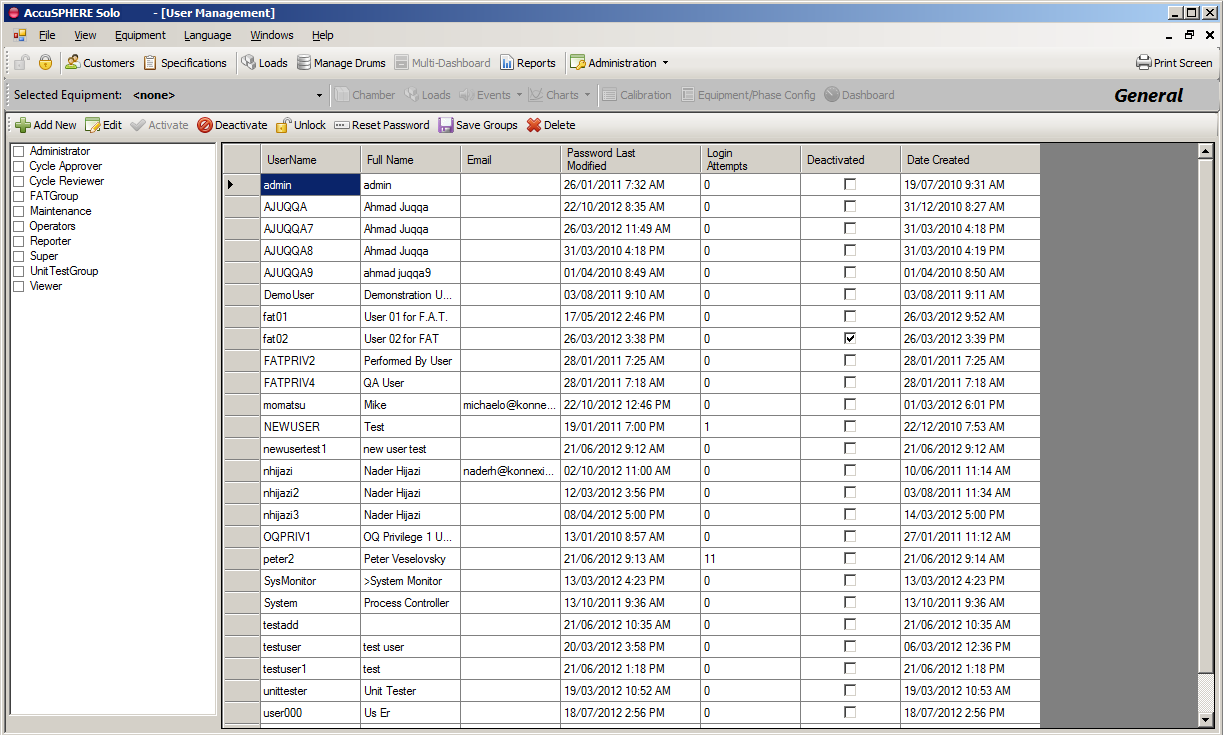
Note: Changing the groups to which a particular user belongs requires that the application be restarted before the changes will take effect.
Adding or Editing a New User
When the User Administration grid is presented, click the “Add New” button to add a new user. To edit a user, click on the user and select “Edit”. The following is available:
-
Username, full name, e-mail, and password
-
The full name will be the name that the system will display associated to user events and reports
-
If an e-mail is entered, the system will send e-mail alerts when certain alarms occur based on the configuration. Konnexis can configure which alarms/events send out e-mail alerts.
-
The password will be that user’s password until they change it. When editing a user, this field is not available: changing the password can only be achieved via the login form, see section Changing or Resetting your Password).
-
For information on how to reset a user’s password, in the event that the user forgets their password, see section Changing or Resetting your Password.
-
-
Select the groups to which the user should belong and click the “Save Groups” button
-
Once a user is added, users with the Deactivate box checked can be activated by highlighting the user and clicking Activate. The checkmark will be removed from the Deactivate column.
-
Active users can be deactivated by highlighting the user and clicking on Deactivate. A check mark will be placed in the Deactivate column.
Note: After a user confirms his/her identity, the Full Name cannot be changed and the field will become read only.
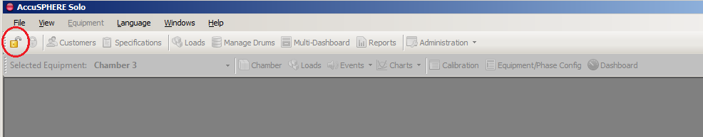
Changing or Resetting your Password
To change your password, execute the following steps:
-
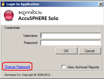
Click the log in button.
-
On the “Login to Application” pop-up, click on “Change Password”:
-
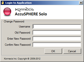
Fill out the required fields and click OK:
If user forgets their password, the user administrator can reset the password via the User Management grid:
-
When the user management grid is presented, select the user and click the “Reset Password” button:
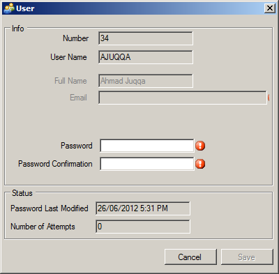
-
Enter the user’s new password, confirm the entry, and click Save:
-
The next time this user attempts to log in, he/she will have to enter the newly reset password after which the application will require them to change the password to one of their own.
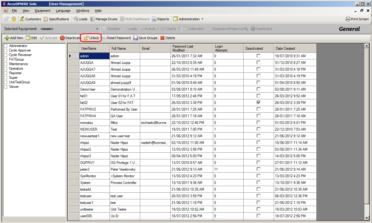
Unlocking a User
If a user enters his/her password incorrectly more than the configured number of times, that user will be locked out until the administrator unlocks them.
Note: The maximum number of allowed login attempts is configured via the System Configuration grid.
If a user becomes locked out, navigate to the User Management grid, select the user and click the Unlock button located on the toolbar. Performing this action will reset the user’s number of login attempts to zero:
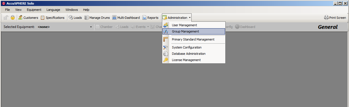
Group Management Form
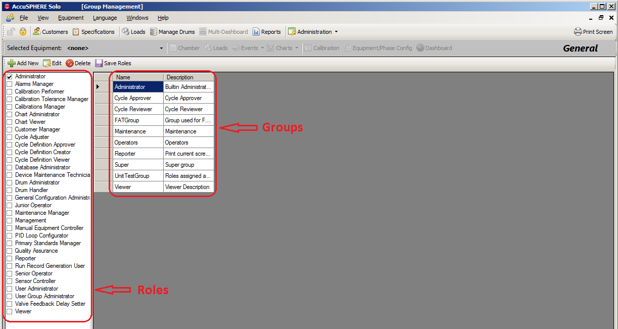
Each user may be associated to a privilege group (or multiple groups). A group can contain multiple roles, i.e. system functions. Groups can be created, edited, and deleted via the Group Management grid. To access the group management grid, click the Administration drop down menu and select “Group Management” as illustrated in the following screenshot:
The group management grid will be displayed. Clicking on a particular group (on the right-side portion of the grid) will show you which roles are currently selected for that grid (a list of roles is displayed on the left-side portion of the grid; roles which are selected for the group have a check mark next to them):
Adding, Editing, and Deleting Groups
To add a group
-
Click Add New
-
On the Group pop-up screen enter Group Name and Description
-
Click Save
To edit a group
-
Highlight the group in the right pane
-
In the left pane place check marks next to the roles to add to the group
-
Click Save Roles
To delete a group
-
Ensure no users or roles are associated to the group
-
When removing a group from multiple users, the Save Groups must be clicked before moving to the next user
-
-
Highlight the group to delete and click Delete
Note: Adding or editing groups requires that the application be restarted before the changes will take effect.
Primary Standard Management Form
This form will allow users to configure primary standards for calibration. Refer to section Primary Standard Maintenance for more information regarding primary standard management.
-
Primary Standard Management
-
A Primary Standard must be created prior to performing calibration.
-
To manage Primary Standards, select Administration > Primary Standard Management
-
New Primary Standard
-
Select New
-
Fill in fields with appropriate information
-
Click Save
-
-
Edit Primary Standard
-
Highlight the Primary Standard and click Edit
-
If the Primary Standard has not been used all fields are available for edit
-
If the Primary Standard has been used only the Calibration Date fields are available for edit.
-
-
Delete Primary Standard
-
Highlight the Primary Standard and click Delete
-
On the confirmation pop-up click Yes
-
-
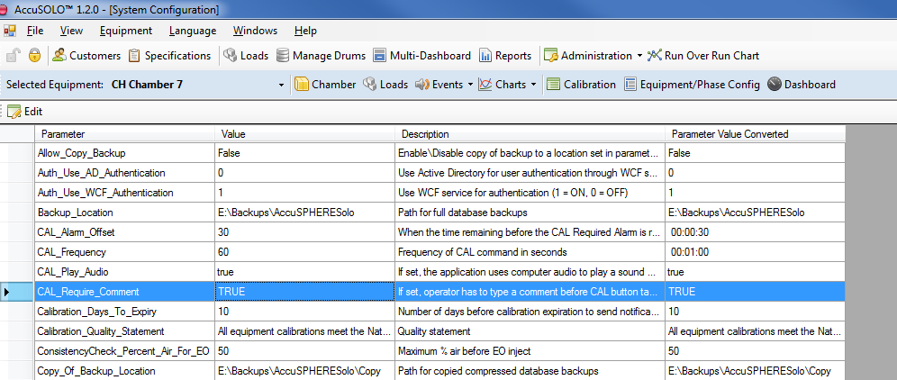
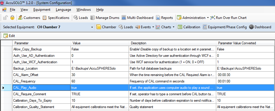
System Configuration Form
To access the system configuration form, select Administration > System Configuration.
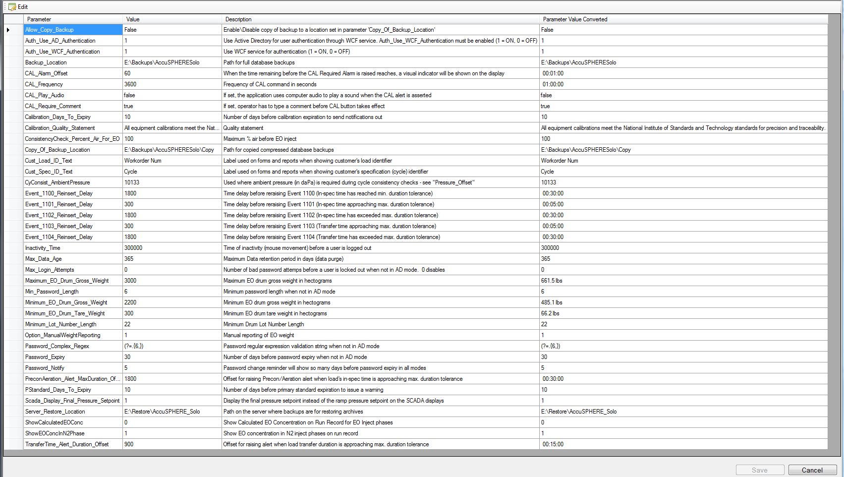
This form will facilitate the following functions:
-
Allow Copy Backup: Enable/Disable copying of a database backup to a location configured in parameter 'Copy_Of_Backup_Location'
-
Auth_Use_AD_Authentication: Use Active Directory for user authentication through WCF service. Auth_Use_WCF_Authentication must be enabled (1 = ON, 0 = OFF)
-
Auth_Use_WCF_Authentication: Use WCF service for authentication (1 = ON, 0 = OFF)
-
Backup Location: Location on the hard drive where full database backup files will be saved
-
Operator Sensor Check “CAL” Function Parameters (see section Operator Sensor Check “Cal” Function for more information):
-
CAL_Alarm_Offset: When the time remaining before the CAL Required Alarm is raised reaches, a visual indicator will be shown on the display
-
CAL_Frequency: Frequency of CAL command in seconds
-
CAL_Play_Audio: If set, the application uses computer audio to play a sound when the CAL alert is asserted
-
CAL_Require_Comment: If set, operator has to type a comment before CAL button takes effect
-
-
Calibration Days to Expiry: System will send a notification this many days before a calibration expires.
-
Calibration Quality Statement: Quality statement that will appear on calibration records.
-
ConsistencyCheck_Percent_Air_For_EO: Maximum % air that cycle consistency check will allow before start of an EO inject phase.
-
Copy of Backup Location: Location on the hard drive where database backups are copied.
-
Cust_Load_ID_Text: Text label that will be used on forms and reports when showing customer's load identifier
-
Cust_Spec_ID_Text: Text label that will be used on forms and reports when showing customer's specification (cycle) identifier
-
Inactivity time: The user will automatically be logged out of the AccuSOLO application after this many seconds of inactivity (i.e. no mouse movement or keyboard strokes take place).
-
Max Data Age: Defines the number of days that data will be stored in the database before it is purged.
-
Max_Login_Attempts: Number of bad password attempts before a user is locked out (when not in Active Directory user authentication mode). Feature can be disabled by setting this value to zero (0).
-
Maximum_EO_Drum_Gross_Weight: Maximum value that can be set for EO drum gross weight (in hectograms) in Drum Management form.
-
Min Password Length: After user changes their password, the new password will be valid for this many days until it expires (i.e. until the system forces password change). Entering zero (0) will disable this feature.
-
Minimum_EO_Drum_Gross_Weight: Minimum value that can be entered for EO drum gross weight (in hectograms) in Drum Management form.
-
Minimum_EO_Drum_Tare_Weight: Minimum value that can be entered for EO drum tare weight (in hectograms) in Drum Management form.
-
Minimum_Lot_Number_Length: Minimum number of characters that system will allow to be entered for Drum Lot Number Length when creating/editing a drum.
-
Password_Complex_Regex: Password regular expression validation string when not in Active Directory user authentication mode.
-
Password_Expiry: Number of days before password expiry when not in Active Directory user authentication mode.
-
Password Notify: When logging in, password-change notification warning will be presented this many days before the password expiry date. Whenever a user attempts to log in this many days before the password expires, the system will present a warning message which will indicate how many more days the password will be valid.
-
PStandard_Days_To_Expiry: Number of days before primary standard expiration to issue a warning.
-
Report_AH_RH: When set to True, the AH and RH measurements will be reported periodically throughout the EO Dwell and EO Dwell with N2 Make-up phases.
-
Scada_Display_Final_Pressure_Setpoint: Display the final pressure set-point instead of the ramp pressure set-point on the SCADA Chamber Status and Dashboard displays.
-
Server_Restore_Location: Path on the server where backups are for restoring archives.
-
ShowEOConcInN2Phase: Show EO concentration in Nitrogen Inject phases on run record.
PLC Configuration
PLC Configuration form is used to define the IP address(es) of PLC(s) for communications. Access the PLC configuration form via the Administration dropdown.
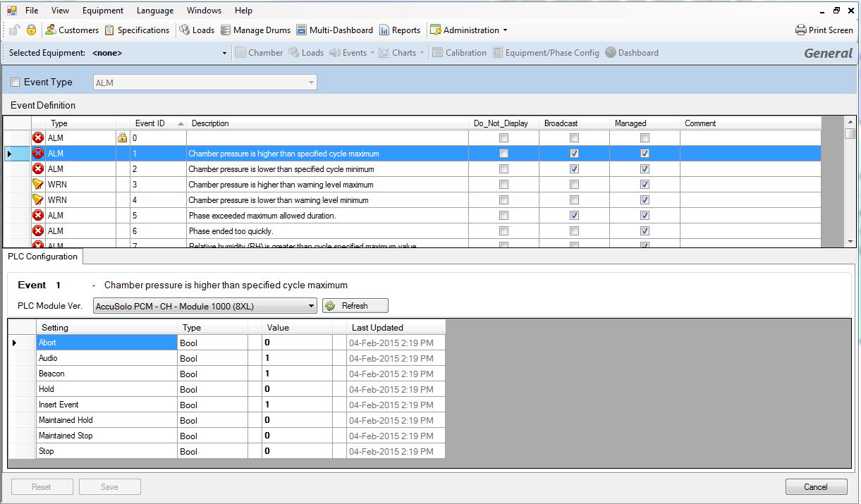
Event Configuration
The event configuration interface is accessed from the Administration drop down menu.
The top frame lists all the events that are exist within the system. The bottom frame allows you to set the PLC configuration for the selected event (e.g. whether it causes a Hold or a Stop mode).
Note: Not all events will apply to your particular configuration of chamber. Some events are only raised if the appropriate Hardware Template and associated devices are installed.
It includes the following features:
-
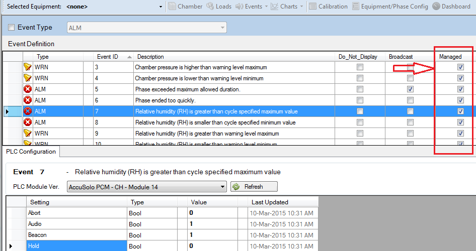
User will have access to viewing and, if license permits, configuring PLC events. The following event properties can be edited as long as the “Managed” property for that event is set (see checkbox in Managed column):
-
Abort – aborts the cycle
-
Audio – activates the audio alarm
-
Beacon – activates the visual beacon
-
Hold – puts chamber on Hold
-
Insert Event – inserts the event into the Run Record report
-
Maintained Hold – keeps chamber on Hold until the event is cleared
-
Maintained Stop – keeps chamber in Stopped mode until the event is cleared
-
Stop – puts chamber in Stopped mode
-
-
Events that are set to “Broadcast” will send a notification e-mail when they occur.
-
Events configured with the “Do Not Display” property set will not appear on any Chamber Status or Dashboard displays (e.g. Current or Historical Events). The event will, however, still appear on the Machine Events report.
-
Display the event type, event ID, and description.
-
If a configuration is changed then the buffer service will update the PLC memory automatically.
-
Buffer service will re-write all event configuration when it starts up provided that:
-
PLC is not blank
-
Watchdog is operating
-
To change the value of an event setting, click the Value field, enter a 1 or 0 (true or false), and then click Save.
Configuration can be changed only for events that have the “Managed” property set:
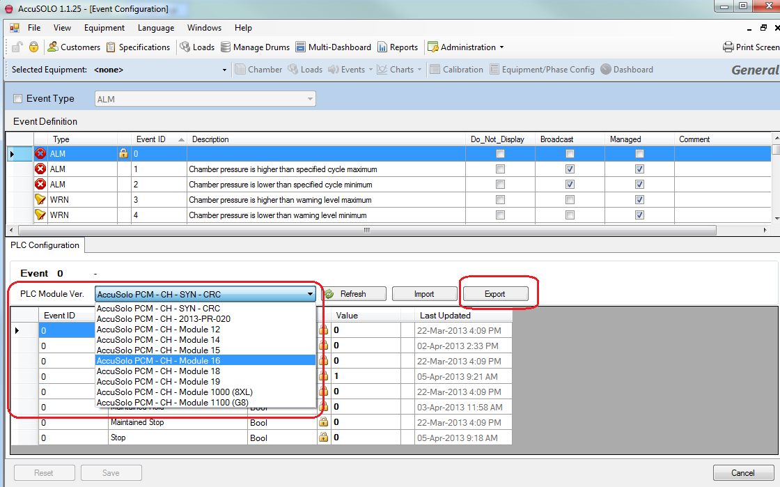
Import/Export of Event Configuration
Using the Event Configuration module, the PLC event configuration can for a specific PLC Module Version can be exported into an XML file that can then be imported on a different site for a different PLC Module Version.
To use the event configuration import/export utility:
-
Navigate to the Event Configuration module (available from the Administration drop-down)
-
If you have multiple PLC Module Versions installed on your site, select the one you wish to export from the “PLC Module Ver.” drop-down and then click the Export button.
-
Save the XML file to your hard-drive. The system will present a message that the event configuration has been exported successfully.
-
Now you can import this XML file on a different site for a different PLC Module Version (or the same site but for a different PLC Module Version). Be sure to select the correct PLC Module Version from the same dropdown menu, click the Import button (next to the Export button) and select the XML file you exported.
-
After successful import, click the “Save” button on the bottom toolbar.
Screens Related to Chamber Equipment
The application will facilitate various screens related to the selected chamber.
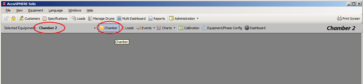
Chamber P&ID Window
To access the Chamber P&ID window, select the desired equipment from the drop-down menu and then click the Chamber icon.
Note: Your site must be configured with the appropriate license to access this window.
This screen will display the status of all devices and equipment related to the chamber. The following functions will be available:
-
Chamber mode selection
-
Cycle start command
-
Cycle abort command
-
Ability to capture the current state of the chamber on the run record
-
Recipe and chamber information:
-
Phase number and name
-
Loop increment
-
Current mode and sequence
-
Cycle time(s)
-
Phase time(s)
-
Indication whether EO has been admitted to the chamber
-
-
Ability to view detailed information on all equipment by double-clicking the selected equipment
-
Ability to manually control a device
-
Ability to set Manual or Auto mode on individual devices (only devices in Manual mode can be controlled, except for EO subsystem equipment)
-
Ability to set the feedback delay times for individual devices
-
Ability to reset timers on individual devices
-
Ability to configure PID loops for proportional valves
-
Ability to enable/disable a sensor
-
-
“Phase Completed” indicator: turns on when the current phase has met all phase completion criteria
-
“Phase Start Interlock” indicator: turns on when the next phase is allowed to start.
Note: If the “Phase Completed Indicator” is ON and the next-phase start-interlock is not satisfied, an alarm is raised.
Device Diagnostics and Manual Control
The Operator will have the ability to manually control a device if manual mode is set on the particular device.
If the device type is a “switch” then the application will allow users with the General Configuration Administrator role to configure the de-bounce timer for the device.
The switch status pop-up window will display the following information:
-
Switch status (on/off)
-
De-bounce time delay (in seconds)
The following switch commands will be available:
-
Set de-bounce time delay.
Note: Manual mode is NOT available for any EO subsystem equipment.
To put a device into Manual mode, ensure that you are logged in with appropriate privilege, double-click the graphical device icon, and then select the “Manual” button.
The following device types are supported:
Motors
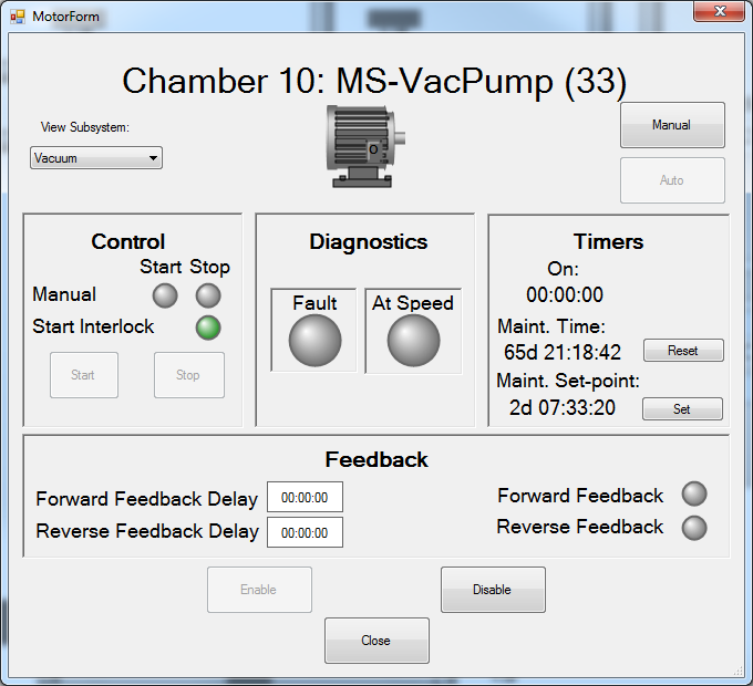
Double click any of the motor icons in order to access that motor’s status pop-up window. The motor status window will display the following information:
-
On/Off Status (typically green and “I” for ON and grey and “O” for OFF)
-
Fault status (typically yellow and “F”)
-
At Speed status
-
Timer:
-
On time – total amount of time in seconds the device has been on
-
Maintenance time – amount of time the in seconds the device has been on (used to determine when maintenance is due; the system will raise an event)
-
-
Forward Feedback status
-
Forward Feedback delay time set-points
-
Manual control status (typically yellow and “M”)
-
Start interlock status
The following motor commands are available:
-
Start/stop motor
-
Reset timers
-
Set maintenance timer set-point
-
Feedback enable/disable
-
Set forward feedback delay time set-points
-
Set Manual or Auto mode for the device
-
Disable or Enable the motor (typically rust colour and “D” for disabled)
Block Valve
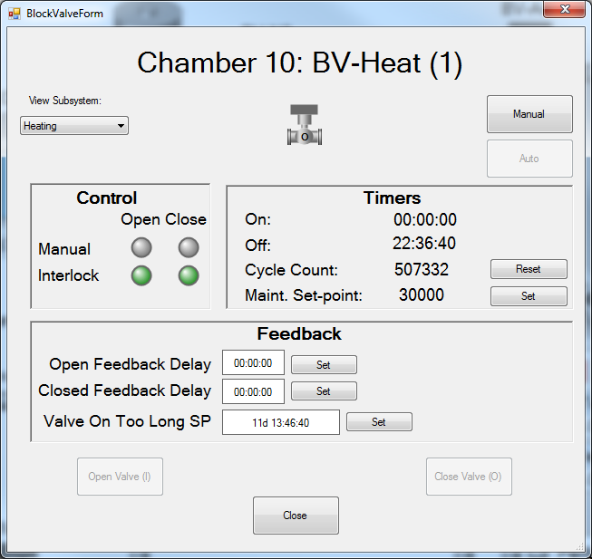
Double-click any of the block valves in order to access that block valve’s status pop-up window. The block valve window will display the following information
-
Open/Closed status (typically green and “I” for ON and grey and “O” for OFF)
-
Fault status (typically yellow and “F”)
-
Timers (on/off time, cycle count)
-
Open/close interlock status
-
Open/Closed feedback status
-
Open/Closed feedback delay time set-points
-
Timers:
-
On time – total amount of time in seconds the device has been on
-
Off time – total amount of time in seconds the device has been off
-
Cycle count – number of times the device has been cycled
-
Maintenance set-point – amount of cycles after which system will raise the maintenance event (used to determine when maintenance is due)
-
Valve On Too Long Set-point – Preset for a secondary timer in seconds. If the on time exceeds this value, an alarm is raised and the chamber goes on Hold. If this value is set to 0, this feature is disabled. This feature is typically enabled only for valves associated with any chamber gas charge in order to prevent over-pressurization. The secondary timer will reset to zero automatically every time the valve closes.
-
The following block valve commands are available:
-
Open/close valve
-
Reset cycle count
-
Set maintenance set-point
-
Set open/closed feedback delay time set-points
-
Set Manual or Auto mode for the device
Proportional Valve
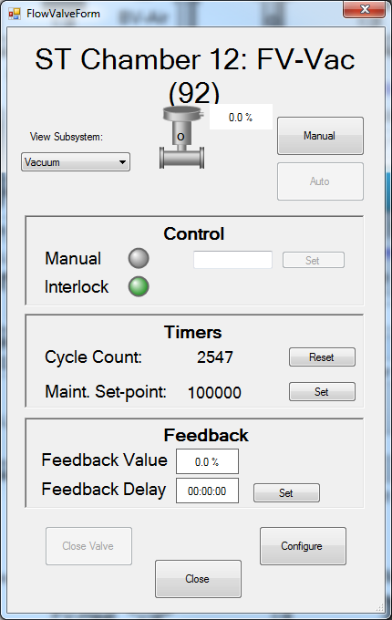
Double click any of the proportional valves in order to access that proportional valve’s status pop-up window. The proportional valve window will display the following information:
-
% Open commanded
-
% Open feedback, if available
-
Fault status (typically yellow and “F”)
-
Open interlock status
-
PID loop values
-
Timers:
-
Cycle count – number of times the device has been cycled
-
Maintenance set-point – amount of cycles after which system will raise the maintenance event (used to determine when maintenance is due)
-
The following proportional valve commands are available:
-
Set % open
-
Close valve
-
Configure PID loop values
-
Set Manual or Auto mode for the device
Sensor

Double click any of the sensor icons in order to access that sensor’s status pop-up window. The sensor status window will display the following information:
-
Sensor reading
-
Sensor Status (enabled/disabled/faulted)
-
Type (controlling or verifying)
The following sensor commands will be available:
-
Enable sensor
-
Disable sensor
IO Status
The I/O status screens will allow the operator to view the diagnostic details. To access this screen, right-click anywhere on the chamber P&ID and select “Show Diagnostics Detail.”
Loads Management
For information on downloading loads to the process controller, refer to section Loads.
The loads management grid will facilitate management of loads. To access the Loads Management module for all loads currently existing in the system, click the “Loads” button in the main toolbar:
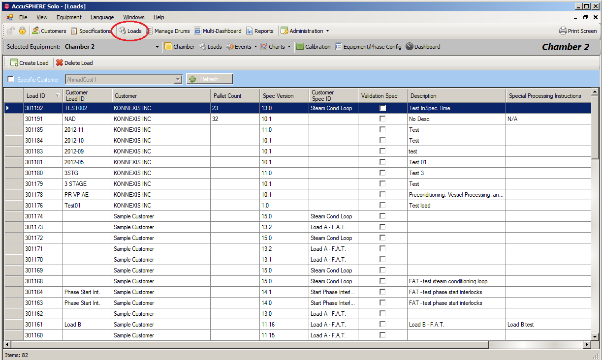
The following information will be displayed for each load:
-
Load number (unique)
-
Customer load ID
-
Customer
-
Specification information for the cycle definition associated to the load:
-
Spec ID (unique cycle definition identifier)
-
Spec Rev (revision of the cycle definition)
-
Customer spec ID
-
-
Whether the associated cycle definition is a validation specification or not.
The following functions will be available:
-
Create a new load by clicking the “Create Load” button:
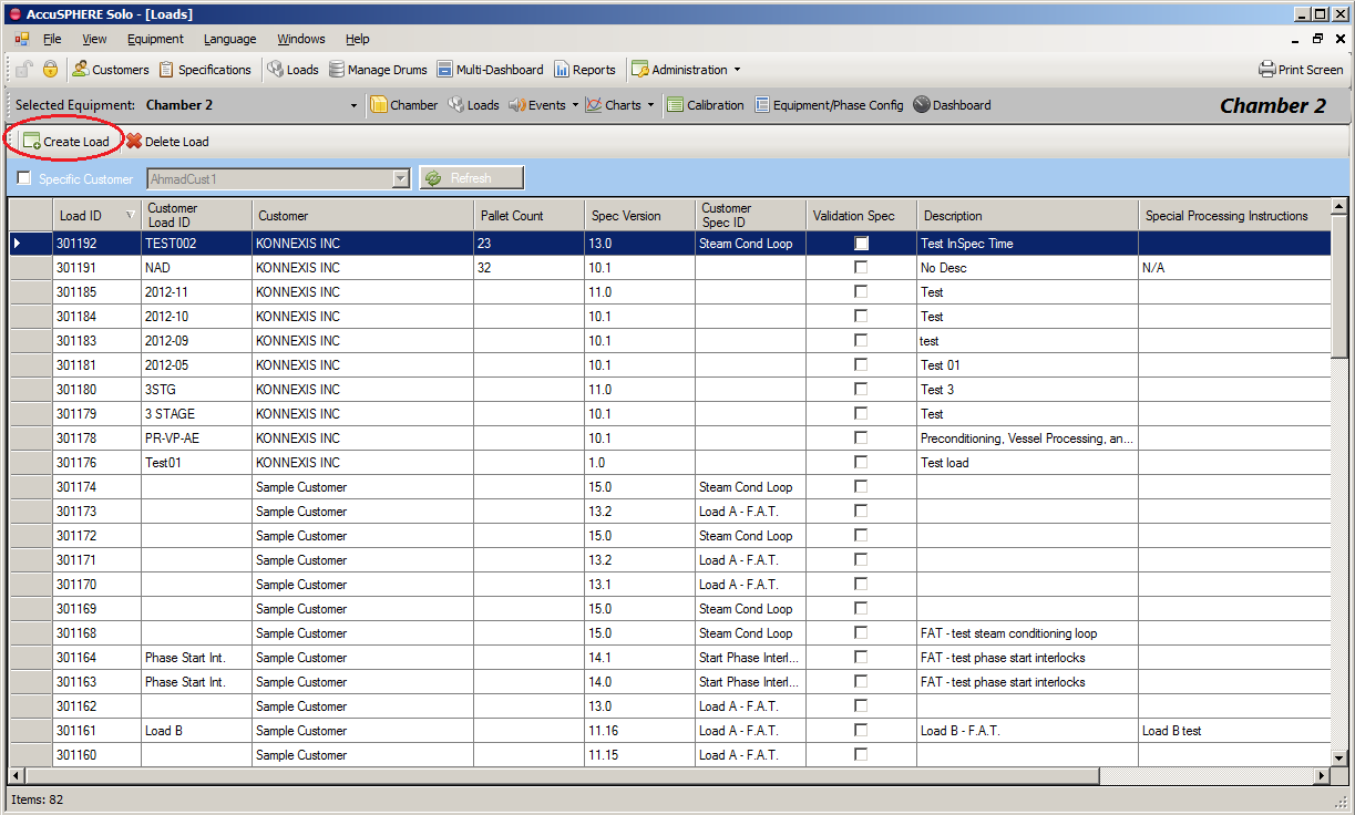
-
A load is created when an approved cycle definition (specification) is associated to customer items
-
Load ID (unique)
-
Customer ID
-
Pallet count
-
Description
-
Special processing instructions
-
Additional information
-
-
Delete a load by selecting the load and clicking the “Delete Load” button.
Note: Only loads that have not been started can be deleted.
Events Module
The application provides information related to current alarms as well as an event history which displays the last 2000 events/alarms. Users can acknowledge alarms.
-
To access the Current Events grid or the Historical Events grid, first select the desired equipment from the drop-down menu and then select Current or Historical events from the Events drop-down menu:
-
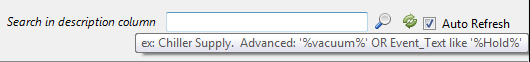
The listed alarms are searchable via the “Search in description column” field at the top of the grid. Enter your search terms and click the search icon to filter results based on your search.
Tip: Hover the mouse over the search field to view examples of how to use search terms. Advanced search queries are also possible:
Example 1: Chiller Supply
Example 2 (Advanced): ‘%vacuum%’ OR Event_Text like ‘%Hold%’
Event Types
The following event types appear on the historical events when they are raised.
|
Event Type ID |
Name |
Icon |
Description |
|---|---|---|---|
|
1 |
ALM |
|
Alarm |
|
2 |
WRN |
|
Warning |
|
3 |
OPR |
|
Operator |
|
4 |
SYS |
|
System |
|
5 |
DVN |
|
Deviation |
|
6 |
CUS |
|
Custom |


-
Active Alarm (ALM):
-
Does not have a “Cleared On” time stamp.
-
Can be acknowledged.
-
Appears on Current Events screen until cleared and acknowledged.
-
Bold red font if unacknowledged.
-
Bold black font if acknowledged.
-
-
Inactive/Cleared Alarm (ALM):
-
Has a “Cleared On” time stamp
-
Can be acknowledged
-
Appears also on Current Events screen until acknowledged
-
Red font if unacknowledged
-
-
Operator Alarm (OPR):
-
User initiated event
-
Only appears in Historical Events, not Current Events
-
Cannot be acknowledged
-
-
System Alarm (SYS):
-
Raised by the system
-
Appears on Current Events screen until cleared and acknowledged
-
Can be acknowledged
-
-
Deviation Alarm (DVN):
-
Appears as a deviation on the Run Record report
-
Does not have a “Cleared On” time stamp
-
Appears on Current Events screen until cleared and acknowledged
-
Can be acknowledged
-
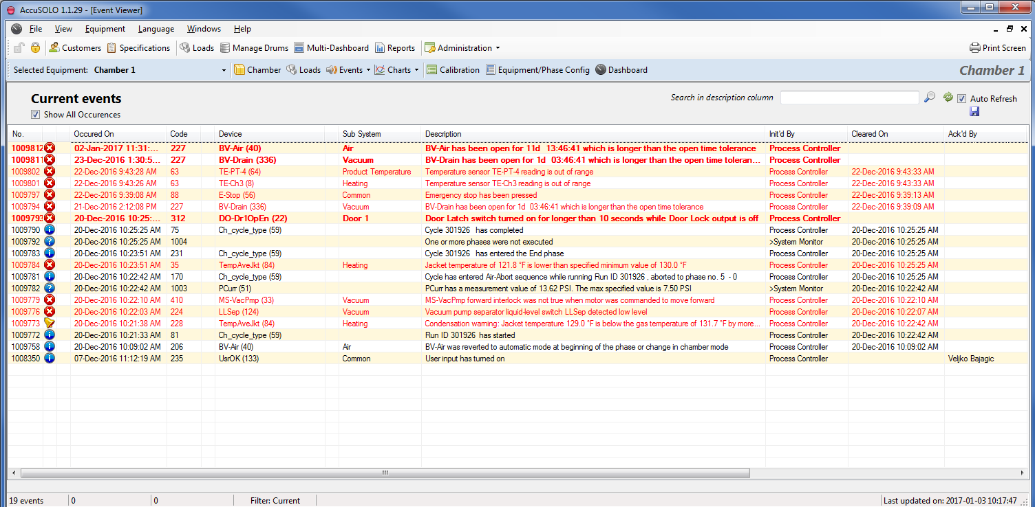
Current Events
The Current Events display will only list events which are not both cleared and acknowledged. Events are considered active (not cleared) as long as the condition which initially raised them persists.
-
Alarm number and code
-
Date/time occurred
-
Device
-
Subsystem
-
Description
-
Initiated by
-
Cleared Date/Time
-
Acknowledged by
-
Alarms that are cleared and acknowledged will only appear on the Event History
-
-
Acknowledged date/time
-
Equipment (chamber)
-
Recurring number
-
Alarm values
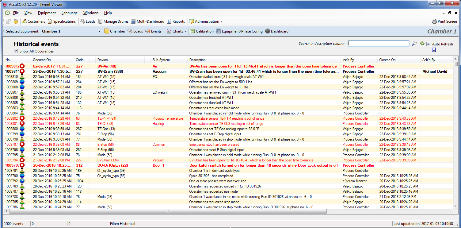
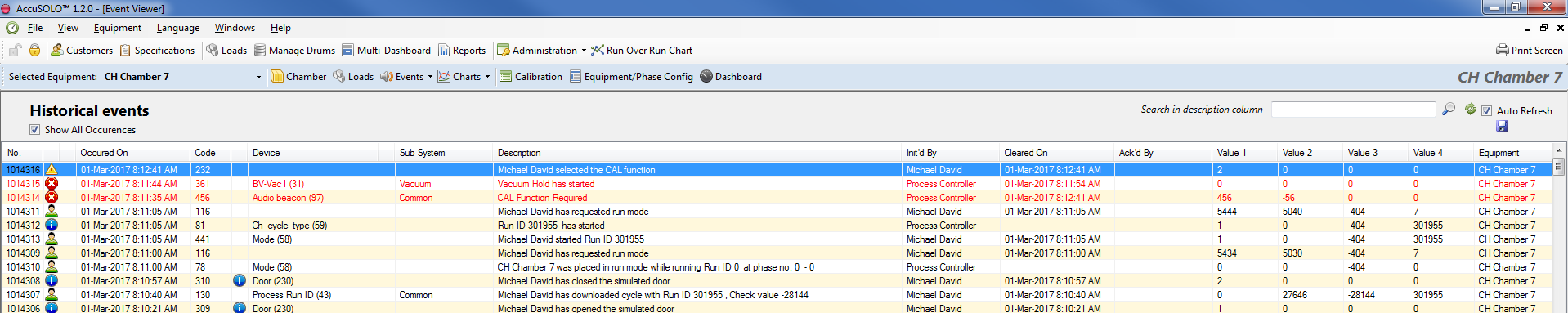
Historical Events
Displays the last 2000 events (all types) including the following information:
-
Alarm number and code
-
Date/time occurred
-
Device
-
Subsystem
-
Description
-
Initiated by
-
Cleared Date/Time
-
Acknowledged by
-
Acknowledged date/time
-
Equipment (chamber)
-
Recurring number
-
Alarm values
Acknowledging and Force Clearing Alarms
An alarm is considered active as long as the condition which raised the alarm persists. The alarm will become automatically cleared once the condition is rectified; ‘Force Clear’ option is also available to users with sufficient privilege by right-clicking on the event.
|
Description |
Font |
Color |
Conditions |
|---|---|---|---|
|
Active Unacknowledged |
Bold |
Red |
Alarm is active, does not have ‘Cleared’ time stamp, and is unacknowledged. |
|
Active Acknowledged |
Bold |
Black |
Alarm is active, does not have ‘Cleared’ time stamp, and is acknowledged. |
|
Inactive Cleared Unacknowledged |
Normal |
Red |
Alarm has both ‘Occurred’ and ‘Cleared’ time stamp. |
|
Inactive Cleared Acknowledged |
Normal |
Black |
Alarm has both ‘Occurred’ and ‘Cleared’ time stamp. |
Alarms which have both cleared and have been acknowledged will appear in regular text and will only be listed in the Historical events.
Three options are available when <<right-clicking>> acknowledgeable events:
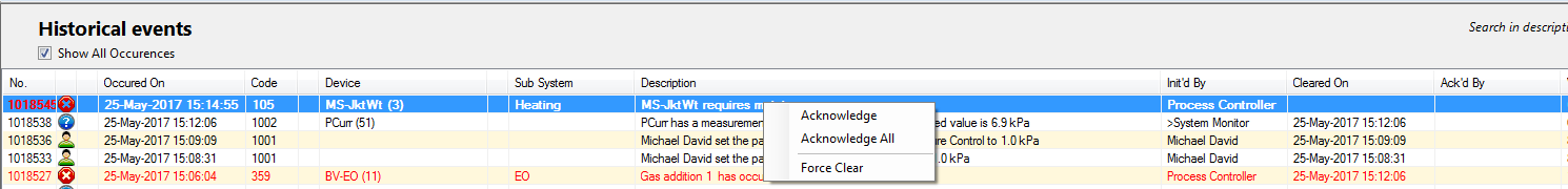
Acknowledge- This will acknowledge the specific event that is clicked on.
Acknowledge All- This will acknowledge all events currently unacknowledged.
Force Clear- This option is only available for users with the appropriate privilege level. This should be used when the event being raised cannot be cleared by any other means. An example of this would be if an event is no longer applicable and the only way to clear the event may be to force it to clear.
Charts
The chamber chart window shows graphically the history of various analog inputs/outputs and thermocouples associated with the chamber. The user may select how many items are shown at any one time. The system supports heart-beat as well as % change triggers for data logging. The user will be able to view logged data for selected devices in a custom date/time range.
To access configured charts, first select the desired equipment from the dropdown menu and then click the Charts drop-down menu:
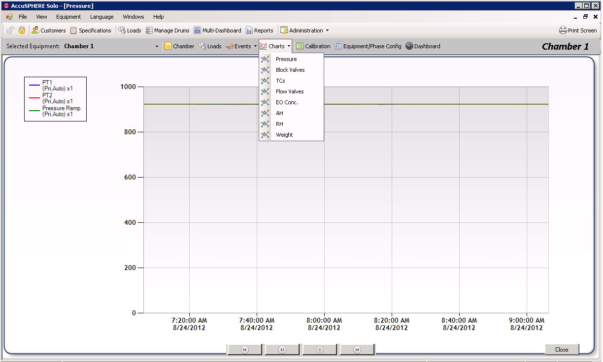
A list of available charts will be presented. Select the device type from the charts dropdown menu to see the configured charts for that particular device type.
Note: DataTrace data can be imported into AccuSOLO charts via the import utility. See section Device Interlock Alarms for more information.
Chart Navigation Buttons
The navigation buttons located along the bottom of the Chamber Chart window allow the user to scroll through time to view available data:
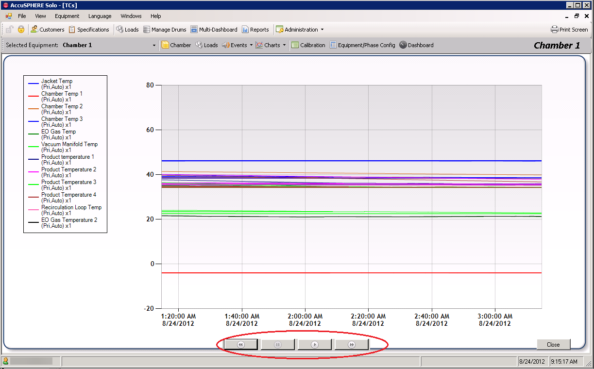
-
To scroll through time, first click the pause
 button so that the chart freezes.
 -
Next, clicking on the
 and
and  buttons will scroll the chart one hour backwards or forwards respectively.
Chart Value Bar
When a chart is presented, left-click anywhere on the chart to display a value bar which will display the date, time, and the value that each device was reading at that particular time stamp, as illustrated by the following screenshot:
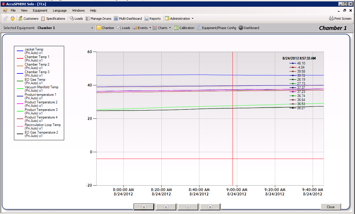
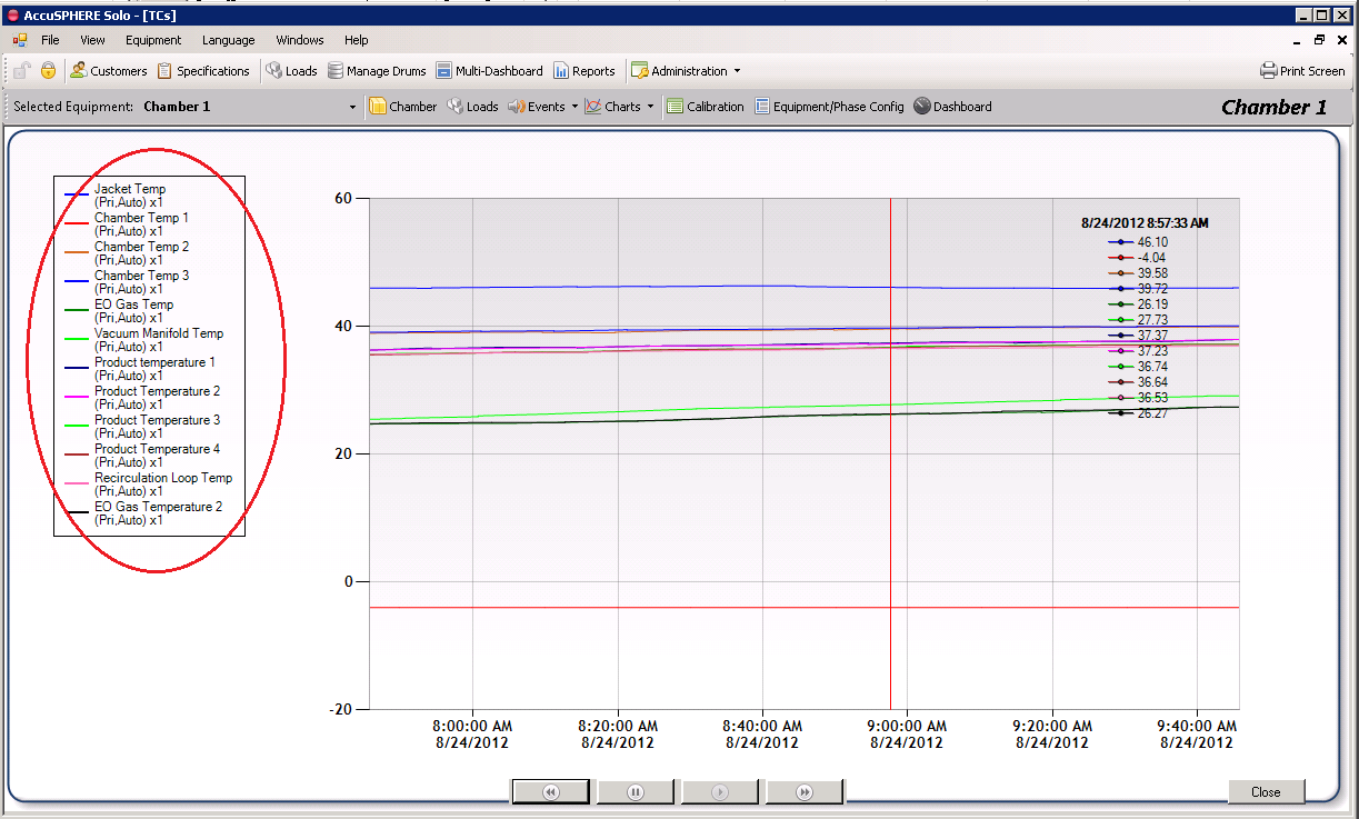
Chart Properties and Legend
A legend located to the left of the chart displays which devices are currently trended on the chart:
To access chart properties, right-click anywhere on the chart and click Properties. The chart properties pop-up will be presented with three tabs:
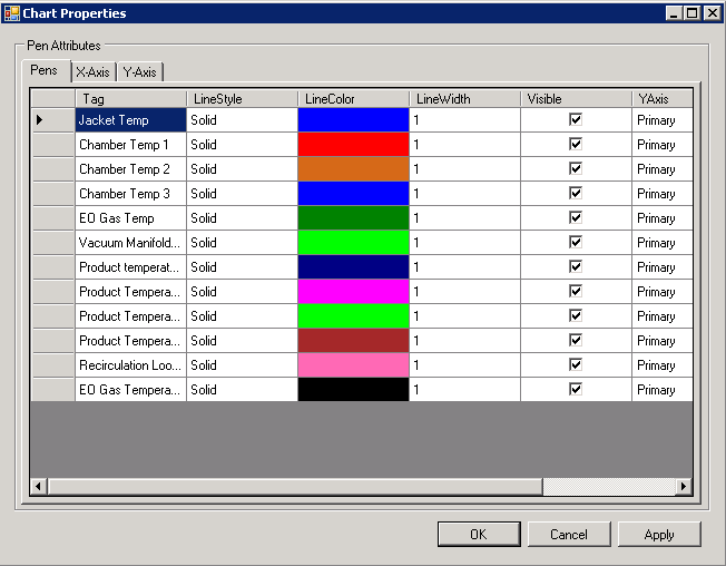
The pens tab (i.e. Pen Attributes) lists the devices shown on the chart and allows you to configure which ones are visible on the chart as well as other properties such as the line style, colour, and width.
Using the pen attributes tab, it is possible to configure a secondary y-axis for each device (i.e. the device will be plotted against a secondary y-axis). The default selection is “Primary”.
It is also possible to configure a multiplier for each device plot which will multiply all readings for the device by the entered value. Scroll the screen to the right to view the multiplier values.
Tip: Right-click anywhere in the chart properties Pens grid to Select or Deselect all “Visible” checkboxes in that column.
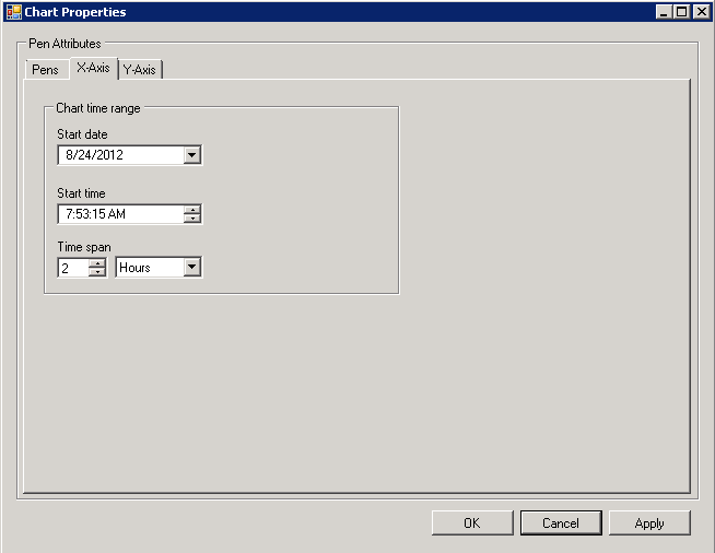
The X-Axis tab allows you to manually configure a chart time range in the x-axis. Input the starting date and time and then select the time span which you wish the chart to display:
The Y-Axis tab allows you to configure a custom primary or secondary y-axis minimum and maximum value range to be displayed on the chart:
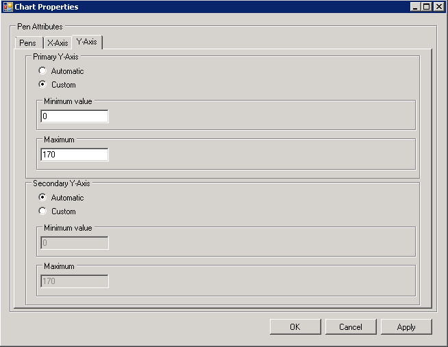
Chart Data Functions
It is possible to export chart data to an XML file by right-clicking and selecting Export Chart Data:
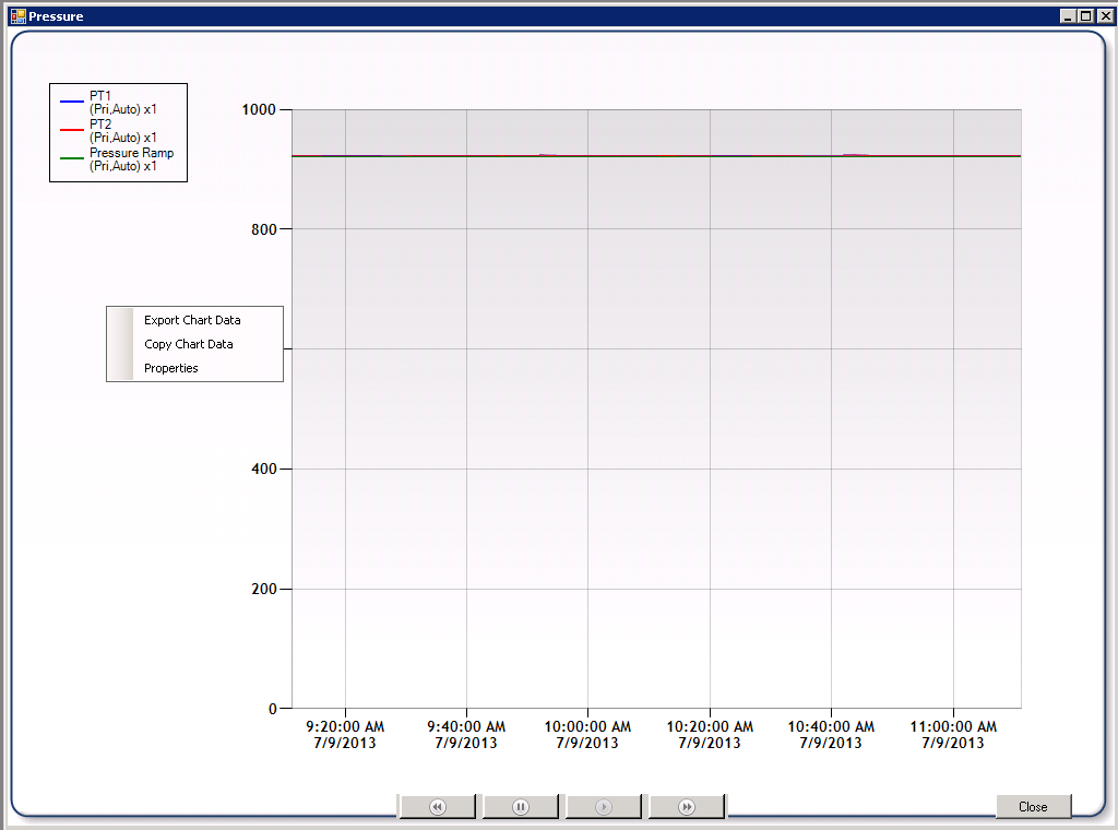
Selecting “Copy Chart Data” will copy chart data to the clipboard. Data copied includes:
-
Measurement value
-
Time interval
-
Device Name and Device ID
The copied data can be pasted into a spreadsheet like Microsoft Excel for further analysis.
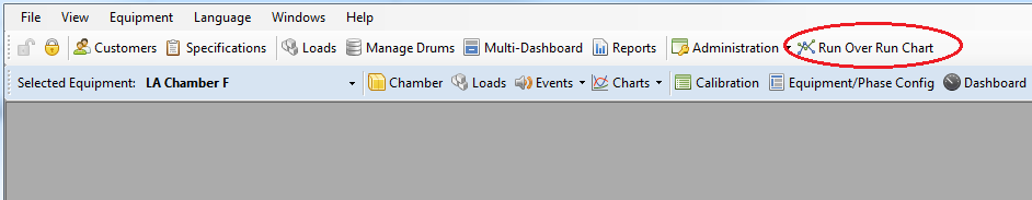
Run over Run Chart Comparison Tool
The Run Over Run Chart Comparison tool can be used to compare two process runs based on an existing equipment chart:
-
To access the tool, click the “Run Over Run Chart” button on the main toolbar:
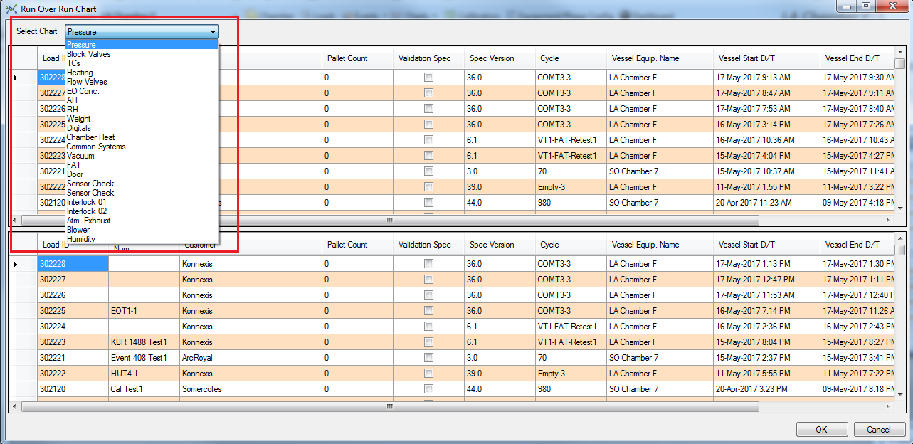
-
On the Run Over Run Chart pop-up, select the chart type from the drop-down:
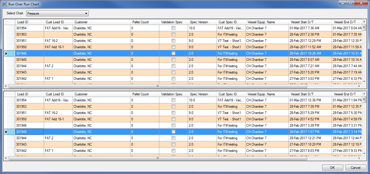
-
Select the first run in the upper frame and then the second run you want to compare with this run in the lower frame:
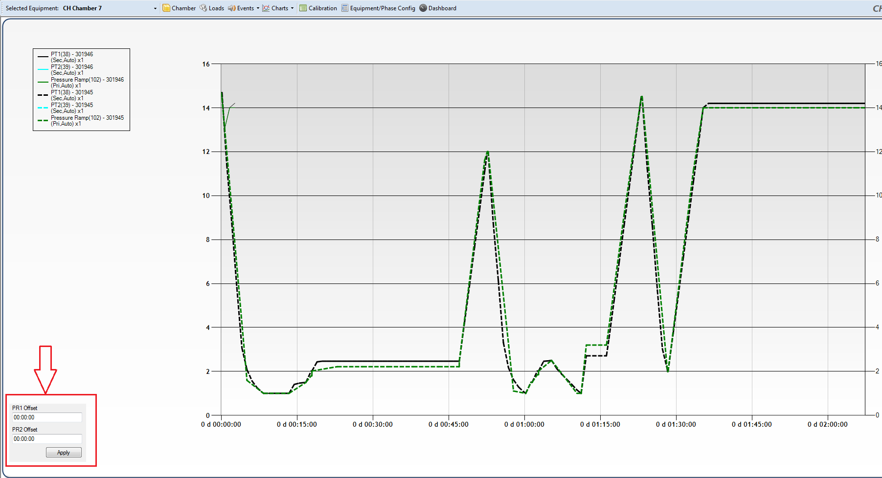
-
Click OK. A chart will be presented that compares the charts from the two runs. The charts can be offset from each other by using the PR1 and PR2 Offset fields in the bottom left corner of the display:
Calibration
Refer to calibration module in section Calibration Module.
Equipment/Phase Configuration
This form facilitates general equipment and phase configuration as described in section Chamber Configuration (Equipment/Phase Config).
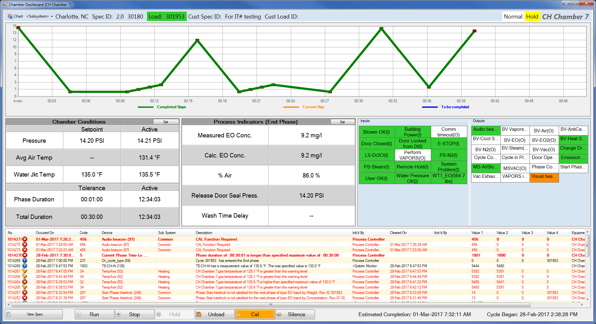
Dashboard
The dashboard provides the following information and functions:
-
Status of all devices filtered on subsystem
-
Chart showing the cycle status with respect to time:
-
Completed steps in the cycle
-
Current steps in the cycle
-
Steps in the cycle that are yet to be completed
-
-
Chamber conditions
-
Pressure ramp or final pressure target set-point, depending on the configuration for your site
-
Currently measured pressure
-
Average chamber air temperature (set-point and measured)
-
Water jacket temperature (set-point and measured)
-
-
Phase specifications for the currently active phase
-
Status of various inputs (if available):
-
Switches related to the door
-
Jacket, nitrogen, and steam flow switches
-
Blower flow switches
-
E-stop
-
Building bower
-
Remote hold
-
System problem
-
Weigh scale reading (double click to access associated drum change functions)
-
-
Status of various outputs:
-
Chamber heating and cooling
-
Door
-
EO/Gas/Nitrogen/Steam block valve and proportional valve status
-
Vacuum valve status
-
Back-vent status
-
Air status
-
Jacket pump status
-
Visual beacon
-
Blower status
-
-
Current Events
-
Ability to start a cycle
-
Ability to place the cycle on Hold/Stop/Run mode
-
Ability to silence an alarm
-
Ability to abort the cycle
-
Ability to capture the current state of the chamber on the run record
-
Estimated cycle completion date/time
-
Date/time stamp of when the cycle was started
-
Print screen
-
Ability to view the cycle definition for the load that is currently in the chamber
-
Ability to change various cycle parameters
-
“Phase Completed” indicator: turns on when the current phase has met all phase completion criteria
-
“Phase Start Interlock” indicator: turns on when the next phase is allowed to start
Note: If the “Phase Completed Indicator” is ON and the next-phase start-interlock is not satisfied, an alarm is raised.
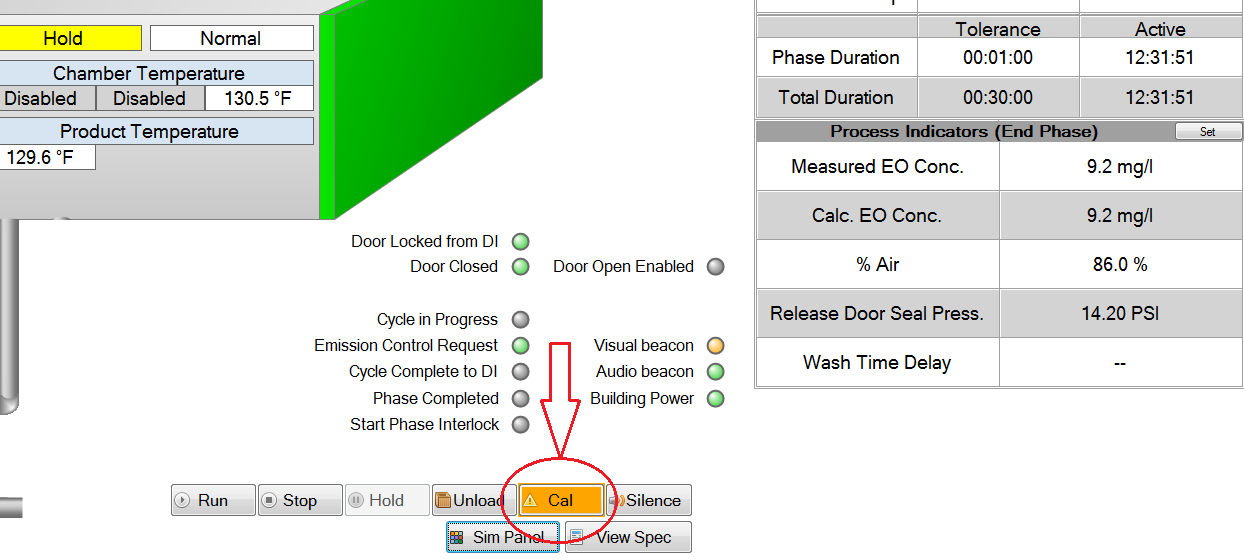
Operator Sensor Check “Cal” Function
The Cal function can be used to provide evidence that a Sensor Check has been performed by the operator on duty. The “CAL” button is available on the Chamber P&ID and Dashboard screens:
The CAL function works as follows:
-
The operator is able to trigger the CAL function at any time during the cycle.
-
When the operator presses the CAL button:
-
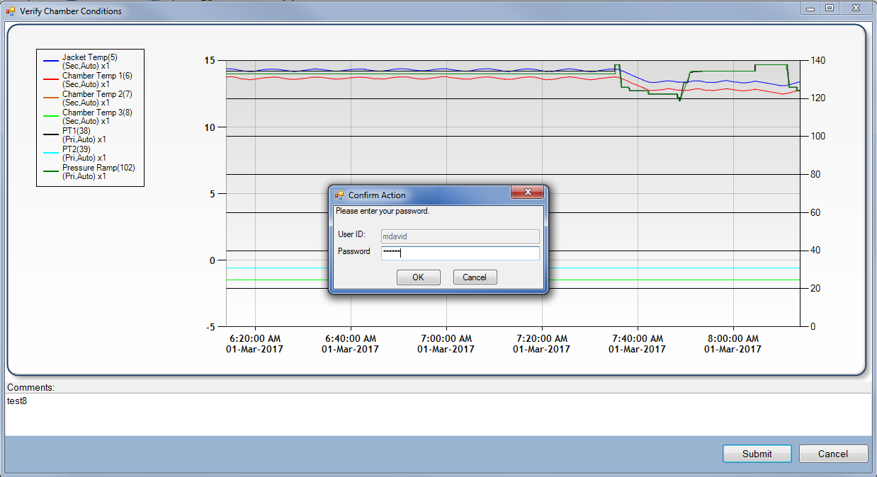
A pre-configured Sensor Check Chart will be displayed indicating a graph of configured values for the past 2 hours
-
The sensors on the chart display are pre-configured by Konnexis only.
-
-
-
A text field is available for the operator to optionally input any comments.
-
A comment will be required if the System Configuration Parameter CAL_Require_Comment is set to TRUE, otherwise it will be optional
-
-
The operator is required to confirm their identity by typing in username and password:
-
At this point, an event log will be created:
-
The operator is able to request the Sensor Check Chart at any time by selecting it from the chart drop-down list.
CAL Alarms and Alerts
The following Configuration Parameters are used to configure CAL alarms and alerts:
-
CAL_Frequency (in seconds)
-
CAL_Alarm_Offset (in seconds)
-
CAL_Play_Audio (Boolean)
The alarms and alerts are implemented as follows:
-
At cycle start, the system starts the CAL Timer counting down from the CAL_Frequency value.
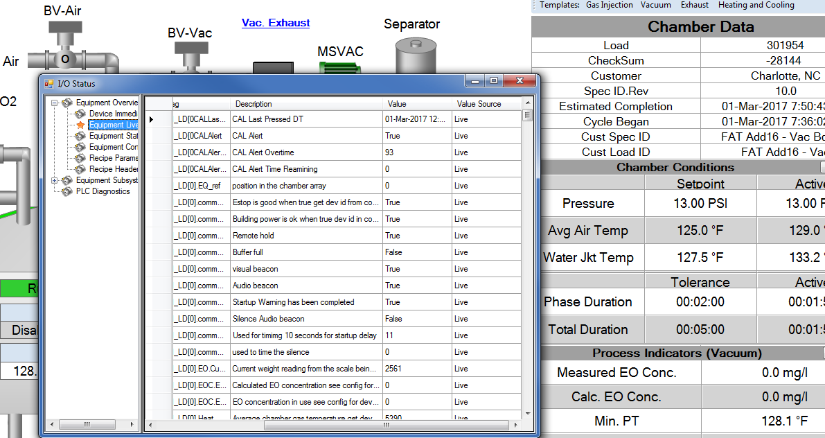
-
The CAL time remaining (i.e. amount of time before “CAL Function Required” alarm is raised) is displayed on the Diagnostic Detail window:
-
-
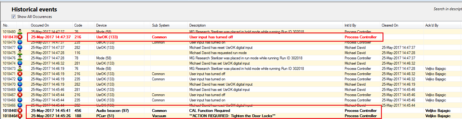
Alarm 232: each time the CAL function is performed, an operator initiated event will be raised, and the CAL Timer will be reset:
-
Alarm 456: if the CAL_Frequency time expires before the operator has had a chance to perform the CAL function, an alarm will be raised (“CAL Function Required”).
-
The CAL Function Required alarm will clear when the operator performs the CAL function at which point the CAL Timer will be reset.
-
-
When the time remaining before the CAL_Frequency time expires reaches a configurable offset (CAL_Alarm_Offset), a visual indicator will be shown on the Chamber P&ID, Dashboard, and Simple Operator Interface. This will cause the CAL button to blink in an amber colour.
-
A PC audio alert will sound if the System Configuration Parameter ‘CAL_Play_Audio’ is set to TRUE:
-
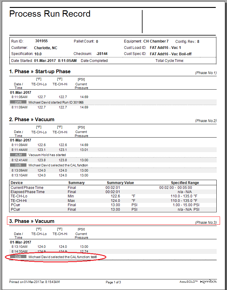
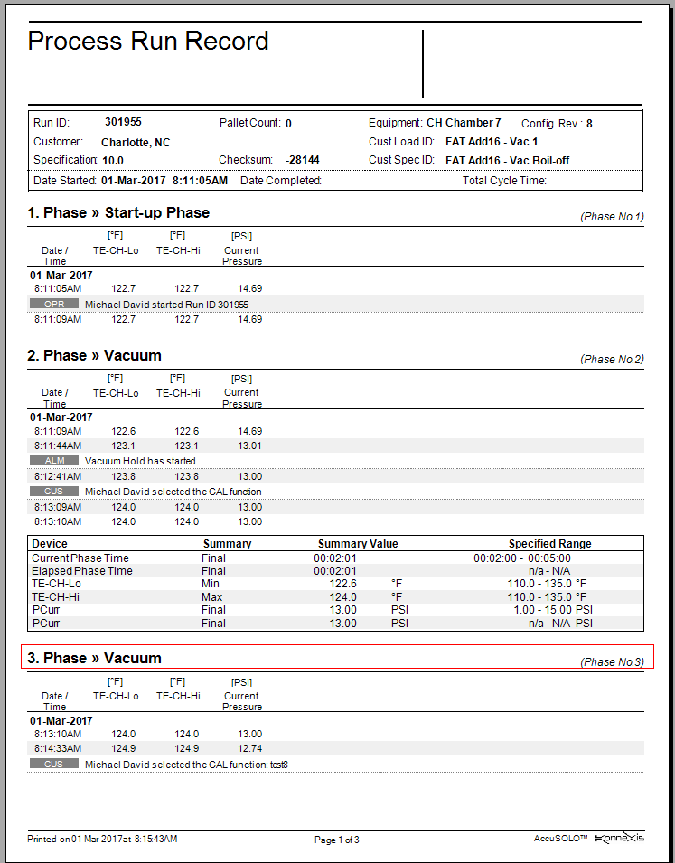
Reporting
The operator initiated CAL event 232 along with username, and comments (if any), will be inserted into the Process Run Record: